Check patentability & draft patents in minutes with Patsnap Eureka AI!

heat sink

A technology for radiators and heat dissipation parts, which is applied in the direction of heat sinks, indirect heat exchangers, heat exchange equipment, etc., which can solve the problems of increased thermal resistance, insufficient heating, and heat transfer of helpless heat pipe groups, so as to increase heat dissipation The effects of sheet area, uniformity of heat input, and excellent cooling performance

Active Publication Date: 2021-10-15
FURUKAWA ELECTRIC CO LTD
View PDF5 Cites 0 Cited by
  • Summary
  • Abstract
  • Description
  • Claims
  • Application Information

AI Technical Summary

Problems solved by technology

That is, in the heat pipe type radiator, there is room for improvement in terms of space saving of the radiator and improvement of cooling performance
[0006] In addition, there is a chamfer on the outer peripheral surface of each heat pipe, and the gap generated outside the chamfer does not help the heat transfer of the heat pipe group, so the volume of the heat receiving part, heat insulation part and heat dissipation part of the heat pipe group cannot be made large enough, There are still cases where sufficient cooling performance cannot be obtained
[0007] Furthermore, if a heat pipe group composed of a plurality of heat pipes is thermally connected to a heat generating body, the amount of heat received by the heat pipes varies according to the distance from the heat generating body.
Therefore, the heat input to the heat receiving part of the heat pipe group cannot be sufficiently uniformed, and since the thermal resistance between the heat receiving part of the heat pipe group and the heat generating body increases, there is a problem that a sufficient improvement in cooling performance cannot be achieved.

Method used


Image

  • heat sink
  • heat sink
  • heat sink

Examples


Embodiment Construction

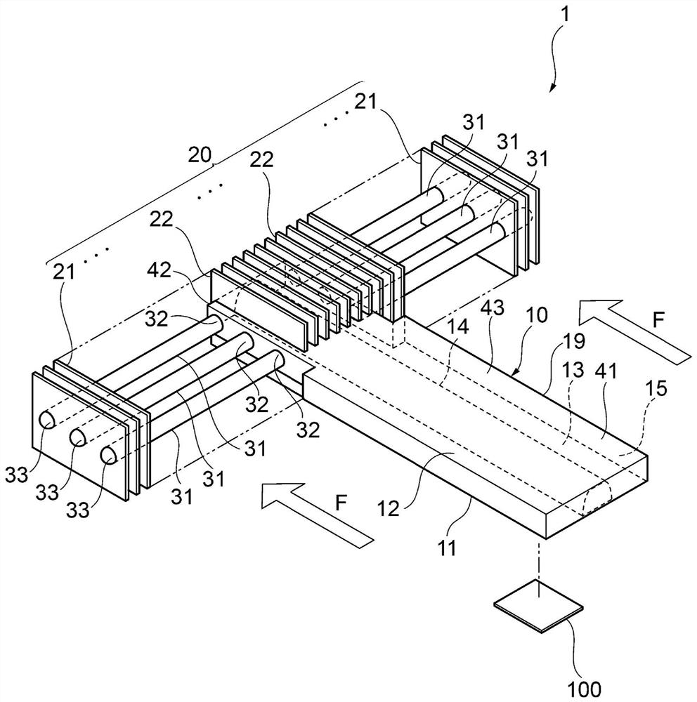
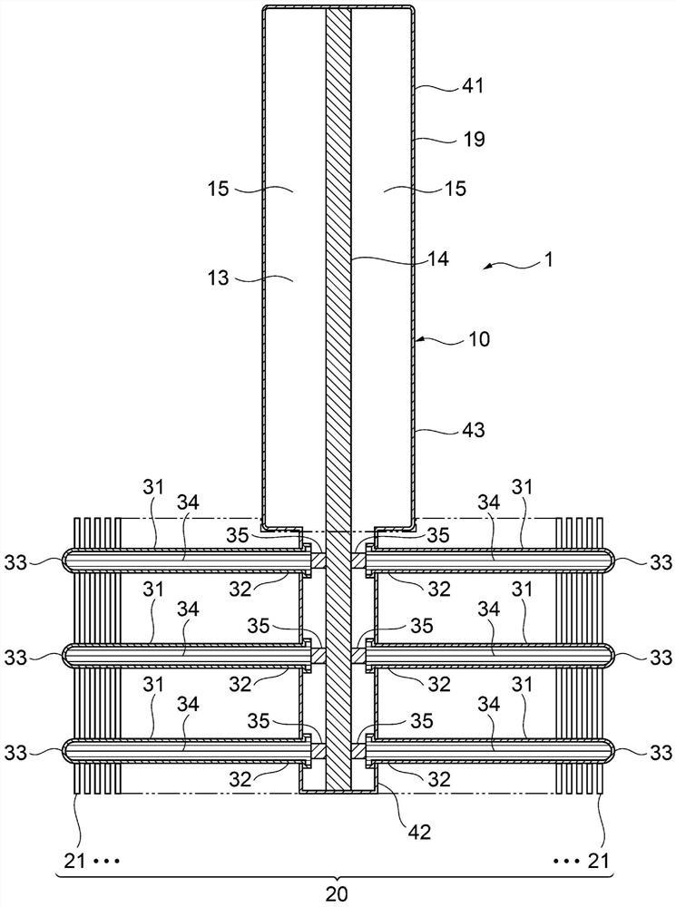
[0044] Hereinafter, a heat sink according to an embodiment of the present invention will be described with reference to the drawings. First, a heat sink according to a first embodiment of the present invention will be described. figure 1 It is a perspective view explaining the outline of the radiator of the first embodiment of the present invention, figure 2 It is a top cross-sectional view explaining the outline of the heat sink according to the first embodiment of the present invention.

[0045] Such as figure 1 As shown, the radiator 1 of the first embodiment of the present invention includes: a heat transfer member 10 having a heat receiving portion 41 thermally connected to the heating element 100 , a heat sink group 20 thermally connected to the heat transfer member 10 , and a heat sink connected to the heat sink. The tube body 31 to which the sheet group 20 is thermally connected. The heat sink set 20 includes a plurality of first heat sinks 21 , 21 . . . installed ...


PUM


Abstract

The present invention provides a heat sink that can obtain a heat receiving part, a heat insulating part, and a heat dissipation part even in an environment where the installation space of the heat sink, especially the installation space in the height direction of the heat sink is limited. While the volume is large enough, the heat sink area of ​​the heat sink is increased. The radiator includes: a heat transfer component with a heat receiving part thermally connected to the heating element; a pipe body connected to the heat dissipation part of the heat transfer part; , the heat transfer component has an integrated internal space that communicates from the heat receiving portion to the connecting portion connected to the pipe body and encloses a working fluid, the internal space of the heat transfer component is connected to the internal space of the pipe body The cross-sectional area of ​​the internal space of the heat dissipation part in a direction perpendicular to the heat transfer direction of the heat transfer part is smaller than the cross-sectional area of ​​the heat insulating part between the heat receiving part and the heat dissipation part.

Description

technical field [0001] The present invention relates to a heat sink for cooling electric / electronic parts and the like. Background technique [0002] As electronic devices become more functional, electronic devices include heating elements such as electronic components, and many components are mounted at high density. In addition, as electronic devices become more functional, the amount of heat generated by heating elements such as electronic components increases. A heat sink may be used as means for cooling a heat generating body such as an electronic component. As the heat sink, generally, a heat pipe type heat sink including a tubular heat pipe is used. [0003] As a heat pipe type heat sink, for example, there is a heat pipe type heat sink in which a plurality of flat fins protrude from an outer peripheral surface provided with a plurality of tubular heat pipes (Patent Document 1). The heat pipe radiator of Patent Document 1 is a radiator that cools the heat generatin...

Claims


Application Information

Patent Timeline
Patent Type & Authority Patents(China)
IPC IPC(8): H05K7/20
CPCH05K7/20336H05K7/20409H01L23/427F28D15/0233F28D15/0275F28D15/046F28D2021/0029F28F1/28F28F3/025F28F2215/00
Inventor 渡边阳介川畑贤也稻垣义胜三浦达朗青谷和明中村敏明
Owner FURUKAWA ELECTRIC CO LTD
Features
  • R&D
  • Intellectual Property
  • Life Sciences
  • Materials
  • Tech Scout
  • Unparalleled Data Quality
  • Higher Quality Content
  • 60% Fewer Hallucinations
Learn More