Liquid hydrogen production facility and hydrogen gas production facility

A technology for manufacturing equipment and liquid hydrogen, which is applied in lighting and heating equipment, hydrogen, liquefaction, etc., and can solve problems such as carbon dioxide treatment that has not been recorded

Pending Publication Date: 2020-11-10
KAWASAKI HEAVY IND LTD
View PDF9 Cites 2 Cited by
  • Summary
  • Abstract
  • Description
  • Claims
  • Application Information

AI Technical Summary

Problems solved by technology

[0004] However, in Patent Document 1, there is no description of the treatment of carbon dioxide generated in the process of generating hydrogen.

Method used


Image

  • Liquid hydrogen production facility and hydrogen gas production facility
  • Liquid hydrogen production facility and hydrogen gas production facility
  • Liquid hydrogen production facility and hydrogen gas production facility

Examples


no. 2 Embodiment approach

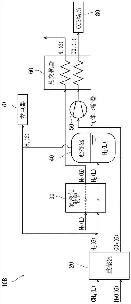
[0048] figure 2 A liquid hydrogen production facility 10B according to a second embodiment of the present invention is shown. In addition, the liquid hydrogen production facility 10B of this embodiment has the same structure as the liquid hydrogen production facility 10A of the above-mentioned first embodiment in many respects. Therefore, the same reference numerals are assigned to the same parts, and the same description will not be repeated.

[0049] In this embodiment, liquid hydrogen H is generated in the hydrogen liquefaction device 30 2 (L) Nitrogen produced during the process N 2 (G) is sent to the heat exchanger 60 . Also, in the present embodiment, the boil-off gas (namely, hydrogen gas H) generated in the reservoir 40 2 (G)) is sent to the flow path toward the hydrogen liquefaction device 30 , or is sent to the generator 70 provided in the liquid hydrogen production facility 10B. Preferably, the boil-off gas is heated to a predetermined temperature and compress...


PUM


Abstract

The present invention is characterized by being equipped with: a reformer for reforming a hydrocarbon to generate hydrogen gas; a hydrogen liquefaction device for liquefying the hydrogen gas to generate liquid hydrogen; a reservoir for storing the liquid hydrogen; and a heat exchanger for carrying out a heat exchange between a boil-off gas produced in the reservoir and carbon dioxide produced in the step in which the hydrogen gas is generated, thereby liquefying the carbon dioxide.

Description

technical field [0001] The invention relates to liquid hydrogen production equipment and hydrogen production equipment. Background technique [0002] Conventionally, there is known a liquid hydrogen production facility that produces hydrogen gas from hydrocarbons (hydrocarbon) and liquefies the hydrogen gas to produce liquid hydrogen. Such liquid hydrogen production equipment is proposed in, for example, Japanese Patent Laid-Open No. 2002-243360 (Patent Document 1). [0003] The liquefied hydrogen manufacturing facility of Patent Document 1 includes: a hydrogen generating device that generates hydrogen from natural gas obtained by gasifying liquefied natural gas; and a hydrogen liquefaction device that liquefies the generated hydrogen. In addition, the liquid hydrogen manufacturing facility further includes a heat exchanger provided between the hydrogen generator and the hydrogen liquefaction device. The heat exchanger supplies hydrogen precooled by exchanging heat between...

Claims


Application Information

Patent Timeline
Patent Type & Authority Applications(China)
IPC IPC(8): F25J1/00C01B3/00C01B3/38C01B32/50
CPCF25J1/001F25J1/0027F25J1/0221F25J1/0236F25J2245/90F25J2210/42C01B32/50C01B3/38C01B3/00C01B3/56Y02E60/32
Inventor 高濑智教林尚一郎森秀树
Owner KAWASAKI HEAVY IND LTD
Why Eureka
Try Eureka