
PCB edge milling machine positioning assembly, positioning method and PCB edge milling machine

A technology for positioning components and positioning methods, applied in positioning devices, metal processing mechanical parts, milling machine equipment, etc., can solve the problems of affecting processing quality, pin-pulling time affecting machine utilization rate and processing efficiency, and high replacement costs. The effect of improving processing utilization, improving service life and saving replacement costs

Active Publication Date: 2020-11-13
SUZHOU VEGA TECH CO LTD
View PDF15 Cites 4 Cited by
  • Summary
  • Abstract
  • Description
  • Claims
  • Application Information

AI Technical Summary

Problems solved by technology

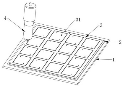
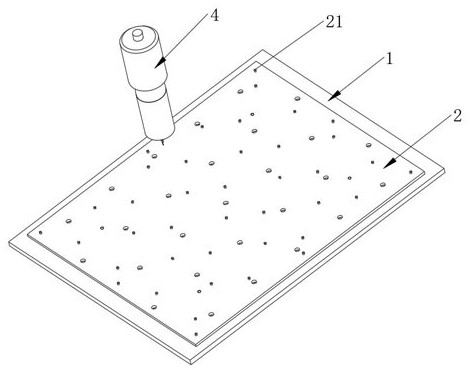
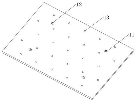
[0004] The purpose of the present invention is to provide a PCB edge milling machine positioning assembly, a positioning method and a PCB edge milling machine, to solve the problem that the existing machine's utilization rate and processing efficiency are affected by the long time of pulling out the pins, and the long-term use of the work surface has problems. Problems affecting processing quality and high replacement costs

Method used


Image

  • PCB edge milling machine positioning assembly, positioning method and PCB edge milling machine
  • PCB edge milling machine positioning assembly, positioning method and PCB edge milling machine
  • PCB edge milling machine positioning assembly, positioning method and PCB edge milling machine

Examples


Embodiment Construction

[0032] The present invention will be further described in detail below in conjunction with the accompanying drawings and embodiments. It should be understood that the specific embodiments described here are only used to explain the present invention, but not to limit the present invention. In addition, it should be noted that, for the convenience of description, only some structures related to the present invention are shown in the drawings but not all structures.

[0033] In the description of the present invention, unless otherwise clearly specified and limited, the terms "connected", "connected" and "fixed" should be understood in a broad sense, for example, it can be a fixed connection, a detachable connection, or an integrated ; It can be a mechanical connection or an electrical connection; it can be a direct connection or an indirect connection through an intermediary, and it can be the internal communication of two components or the interaction relationship between two ...


PUM


Abstract

The invention belongs to the related field of PCB machining equipment, and discloses a PCB edge milling machine positioning assembly, a positioning method and a PCB edge milling machine. The PCB edgemilling machine positioning assembly comprises a working table surface and a jig. A plug is detachably arranged on the working table surface and is used for punching a first pin. The jig is fixed to the working table surface through the first pin, and a plurality of second pins are arranged on the jig and are used for fixing a PCB board to be processed. According to the PCB edge milling machine positioning assembly, the positioning method and the PCB edge milling machine, when the whole machining coordinate position is changed, only the plug is replaced without replacing the working table surface, the replacement operation is simple, and the replacement cost of the working table surface is saved. At the same time, due to the arrangement of the jig, the number of pin holes in the working table surface can be reduced, the service life of the working table surface is prolonged, only corresponding jigs need to be replaced without replacing the working table surface with regard to machiningof PCB boards of different specifications and varieties to complete the machining of the PCB boards of different varieties, pins do not need to be punched and pulled frequently, and the equipment machining utilization rate is improved.

Description

technical field [0001] The invention relates to the related field of PCB processing equipment, in particular to a PCB edge milling machine positioning component, a positioning method and a PCB edge milling machine. Background technique [0002] The PCB edge milling machine cuts the formed PCB large sheet into multiple small units according to the established processing route. The forming method of traditional gong machine: use the spindle to punch pin holes on the workbench panel (usually Bakelite, which is a consumable product), and then plant the pins on the panel. The pin position is the same as the pin on the PCB large board. The holes correspond one by one, and then the large PCB sheet is placed on the pins of the panel for forming processing. In addition, each small unit contains at least two positioning pins, and there will be multiple positioning pins outside the shape of the small unit, and these positioning pins are also fixed on the panel, so that the large PCB c...

Claims


Application Information

Patent Timeline
Patent Type & Authority Applications(China)
IPC IPC(8): B23C3/12H05K3/00B23Q3/06
CPCB23C3/12B23Q3/06B23Q3/062H05K3/00H05K3/0044H05K3/0055
Inventor 庞士君
Owner SUZHOU VEGA TECH CO LTD
Learn More