Blade clamping device

A clamping device and blade technology, which is applied in workpiece clamping devices, grinding workpiece supports, manufacturing tools, etc., can solve the problems of difficult adjustment of the measurement process, long fixture manufacturing period, loss of blade working surface, etc., to reduce production costs and production cycle, reduce the time for changing fixtures, and improve work efficiency

Active Publication Date: 2020-11-13
AECC SHENYANG ENGINE RES INST
View PDF7 Cites 1 Cited by
  • Summary
  • Abstract
  • Description
  • Claims
  • Application Information

AI Technical Summary

Problems solved by technology

[0002] When measuring or polishing the blade, it is necessary to clamp and fix the blade. Since the blade body of the blade is a thin-walled rotating surface, the blade body cannot be clamped. The tongue and groove part of the blade is a symmetrical curved surface, which is relatively thick and can be Clamping, but at the same time, the working surface of the tenon and groove is also the benchmark for measurement or processing. There are also shortcomings in using the working surface of the tenon and groove as the clamping positioning surface, which brings inconvenience to the measurement
[0003] Most of the existing blade clamping and tooling technologies use the working surface of the blade tenon and groove for clamping and positioning, and its disadvantages are: it is easy to cause damage to the blade working surface; different blades require different tooling, the cost is high and the fixture manufacturing period is long ;The structure is relatively complex, and the actual operation is more limited by space factors; for the measurement tasks with a large number of parts and large volume, the measurement process is not easy to adjust and the efficiency is low

Method used


Image

  • Blade clamping device
  • Blade clamping device
  • Blade clamping device

Examples


Embodiment Construction

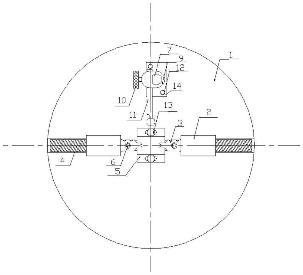
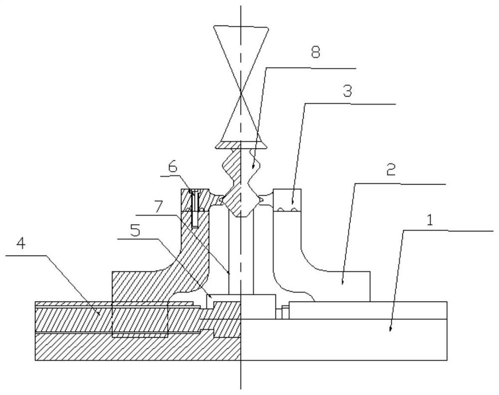
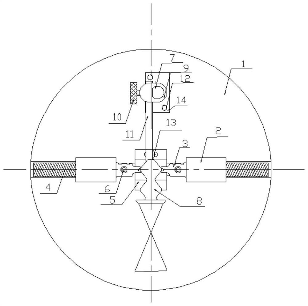
[0029] In order to make the purpose, technical solution and advantages of the application more clear, the technical solution in the embodiment of the application will be described in more detail below in conjunction with the drawings in the embodiment of the application. In the drawings, the same or similar reference numerals denote the same or similar elements or elements having the same or similar functions throughout. The described embodiments are some, but not all, embodiments of the application. The embodiments described below by referring to the figures are exemplary, and are intended to explain the present application, and should not be construed as limiting the present application. Based on the embodiments in this application, all other embodiments obtained by persons of ordinary skill in the art without creative efforts fall within the protection scope of this application. Embodiments of the present application will be described in detail below in conjunction with th...


PUM


Abstract

The invention belongs to the technical field of aircraft blade clamps, and particularly relates to a blade clamping device. The blade clamping device comprises a base, a screw rod, clamping blocks, Y-shaped chucks and an ejector rod assembly. The screw rod comprises a polished rod section and two threaded sections arranged at the two ends of the polished rod section correspondingly, the polished rod section and the two threaded sections are correspondingly arranged in a mounting groove of the base, and the polished rod section is clamped in the mounting groove through a positioning block, so that the screw rod can only rotate in the mounting groove; threaded holes are formed in the bottom ends of the clamping blocks, positioning grooves are formed in the top ends of the clamping blocks, and the two clamping blocks are oppositely arranged on the two threaded sections through the threaded holes in the bottom ends correspondingly; the two Y-shaped chucks are separately mounted in the positioning grooves of the corresponding clamping blocks; and a positioning seat of the ejector rod assembly is fixed to the base, a supporting rod is mounted on the positioning seat, the supporting rod is sleeved with a movable block in a sliding mode, and after the position of the movable block is adjusted, an ejector rod and the supporting rod are fixed through an adjusting nail. According to the blade clamping device, the non-working face of a blade is used for positioning, and data acquisition of the whole working face can be achieved.

Description

technical field [0001] The application belongs to the technical field of aircraft blade clamps, and in particular relates to a blade clamping device. Background technique [0002] When measuring or polishing the blade, it is necessary to clamp and fix the blade. Since the blade body of the blade is a thin-walled rotating surface, the blade body cannot be clamped. The tongue and groove part of the blade is a symmetrical curved surface, which is relatively thick and can be Clamping, but at the same time, the working surface of the tenon and groove is also the benchmark for measurement or processing. There are also shortcomings in using the working surface of the tenon and groove as the clamping positioning surface, which brings inconvenience to the measurement. [0003] Most of the existing blade clamping and tooling technologies use the working surface of the blade tenon and groove for clamping and positioning, and its disadvantages are: it is easy to cause damage to the blad...

Claims


Application Information

Patent Timeline
Patent Type & Authority Applications(China)
IPC IPC(8): B25B11/00B24B41/06
CPCB25B11/00B24B41/068
Inventor 李玉明陈鹏魏兴郭佳骥王博曲磊陈国军孙振兴俞刚俊
Owner AECC SHENYANG ENGINE RES INST
Why Eureka
Try Eureka