
A solid-liquid separation trash can for municipal environmental protection

A technology of solid-liquid separation and trash cans, which is applied in the field of trash cans to achieve the effect of improving the use effect

Active Publication Date: 2022-08-05
深圳市先达威环境产业有限公司
View PDF16 Cites 0 Cited by
  • Summary
  • Abstract
  • Description
  • Claims
  • Application Information

AI Technical Summary

Problems solved by technology

[0004] The object of the present invention is to provide a kind of solid-liquid separation trash can for municipal environmental protection, to solve the relevant problems raised in the above-mentioned background technology

Method used


Image

  • A solid-liquid separation trash can for municipal environmental protection
  • A solid-liquid separation trash can for municipal environmental protection
  • A solid-liquid separation trash can for municipal environmental protection

Examples


Embodiment 1

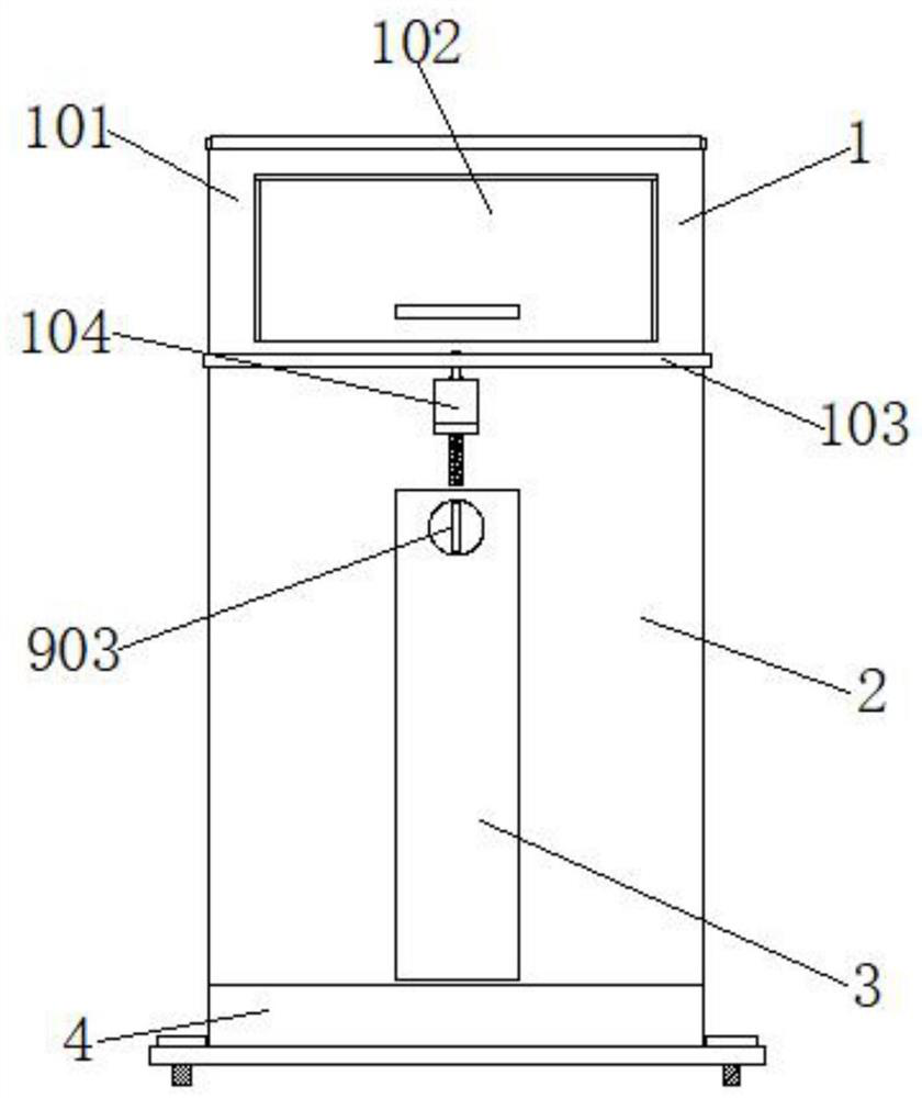
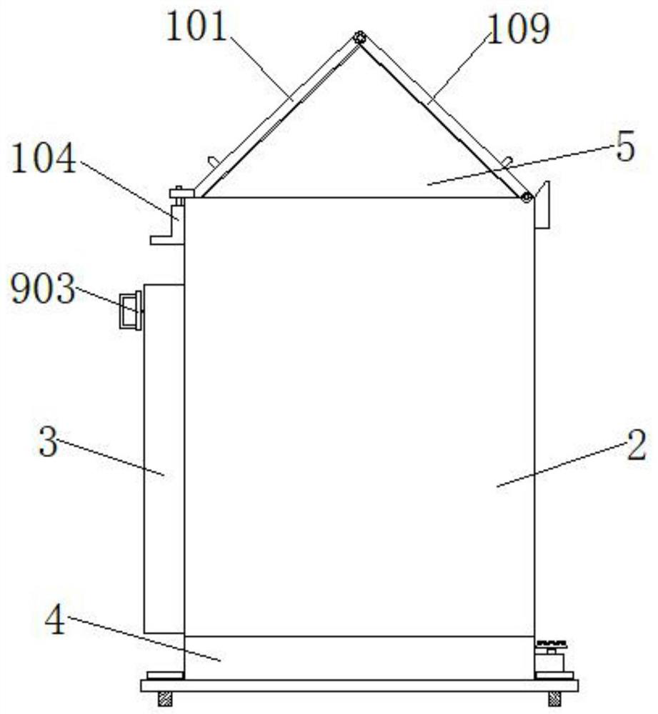
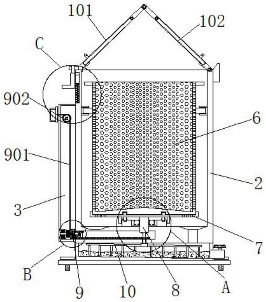
[0035] Example 1, as Figure 1-7 As shown, before cleaning the garbage inside the trash can 6, first manually pull the pull rope 901 to the outside of the installation bin 3 through the handle 903, thereby driving the spool 904 to rotate clockwise on the outside of the rotating shaft B906, at this time the coil spring 907 is gradually wound up to store a certain amount of kinetic energy, and because the one-way gear A910 and the one-way gear B25 are in a clamped state, the rotating shaft D21 is driven to follow the rotation. Drive the rotating shaft E24 to rotate, the rotating shaft E24 is driven by the pulley 14 and the belt 19, so that the rotating shaft C13 and the rotating shaft A8 move and follow the rotation, and the rotating shaft A8 drives the turntable 7 and the trash can 6 on the top of the turntable 7 to rotate, and the centrifugal force generated during the rotation of the trash can 6 The liquid that still exists in the garbage is forced to be thrown out, and when ...

Embodiment 2

[0036] Example 2, as Figure 1-8 As shown in the figure, when the garbage inside the trash can 6 is cleaned, the hand push plate 104 is manually pushed down to release the limiting effect on the cover plate A101, and then the cover plate A101 and the cover plate B109 are bent and overlapped, and the The cover plate A101 and the cover plate B109 are rotated and moved to the end away from the installation bin 3, and the upper part of the main body box 2 is completely exposed, so that the cleaning personnel can take out the trash can 6 from the main body box 2 and dump the garbage, and then pass the garbage to the main body box. The inside of 2 is flushed with clean water, and the rotating shaft C13 is rotated by manually pulling the pull rope 901. During the rotation of the rotating shaft C13, the rotating shaft C13 drives the installation rod 10 and the stirring rod 18 inside the liquid storage tank 4 to rotate together, so that the stirring rod 18 rotates together. The sewage ...


PUM


Abstract

The invention provides a solid-liquid separation trash can for municipal environmental protection, comprising a main body box, a liquid storage bin is installed at the bottom of the main body box, an installation bin is installed at the middle position of one end of the main body box, and the top of the main body box is installed Side baffles are installed symmetrically on both sides of the main body box, a barrel cover assembly is arranged on the top of the main body box, a mounting seat is installed at the center of the bottom of the main body box, and a rotating shaft A is arranged at the center position of the top of the mounting seat, A turntable is installed on the top of the rotating shaft A. The present invention realizes the use of the main body box, the installation bin, the through hole B, the square groove, the belt, the installation groove B, the rotating shaft D, the bevel gear A, the bevel gear B, the rotating shaft E and the one-way gear B. The solid-liquid separation can prevent the garbage with a large amount of liquid and accelerate the corruption and affect the surrounding air environment, which also improves the use effect of the solid-liquid separation trash can for the entire municipal environmental protection.

Description

technical field [0001] The invention relates to the technical field of trash cans, in particular to a solid-liquid separation trash can for municipal environmental protection. Background technique [0002] Trash cans, also known as waste bins or trash cans, refer to the place where garbage is placed. Most of them are made of metal or plastic. When used, put them in plastic bags. When there is too much garbage, you can tie up the bags and throw them away. The container that hides dirt and filth is also a reflection of social culture. [0003] At present, most of the garbage cans for municipal environmental protection directly contain the garbage. Because the traditional garbage cans are mostly closed bucket structures, the liquid in the garbage cannot be separated. If the liquid in the garbage cannot be separated from the solid garbage in time, it will be It makes the garbage with liquid more perishable and easily affects the surrounding air environment; and the liquid separ...

Claims


Application Information

Patent Timeline
Patent Type & Authority Patents(China)
IPC IPC(8): B65F1/16B65F1/00B65F1/14B65F7/00B01D33/11
CPCB65F1/1646B65F1/00B65F1/14B65F7/00B01D33/11Y02W30/10
Inventor 李习勇黄振梅王桂玲
Owner 深圳市先达威环境产业有限公司
Learn More