
Equipment for automatically separating and unloading stacked basket bodies

An automatic separation and equipment technology, applied in loading/unloading, conveyor objects, transportation and packaging, etc., can solve the problems of high work intensity, harsh working environment, multiple auxiliary equipment, etc., to facilitate workshop layout and avoid damage to the basket The effect of physical and high degree of automation

Active Publication Date: 2020-11-13
JIANGSU DEEPAGRI INTELLIGENT TECH CO LTD
View PDF7 Cites 0 Cited by
  • Summary
  • Abstract
  • Description
  • Claims
  • Application Information

AI Technical Summary

Problems solved by technology

[0002] At present, on the production line of the poultry processing workshop, chickens and ducks are transported by special baskets. Generally, stacks of duck baskets are automatically transported to a high place through lifting equipment, and then manually transported to the conveyor belt one by one. The working environment on site is harsh, and workers High work intensity and long working hours
There is a separating device in the prior art, which can lift up all the duck baskets in a stack except the bottom one, then push out the bottom duck baskets, and then put down the bottom duck baskets one by one to realize the automatic separation of the stacked baskets , but this kind of method of separating duck baskets from the bottom requires more auxiliary equipment, including grabbing devices and conveying devices. The overall equipment takes up a lot of space and requires high investment, which is generally unaffordable for factories.

Method used


Image

  • Equipment for automatically separating and unloading stacked basket bodies
  • Equipment for automatically separating and unloading stacked basket bodies
  • Equipment for automatically separating and unloading stacked basket bodies

Examples


Embodiment 1

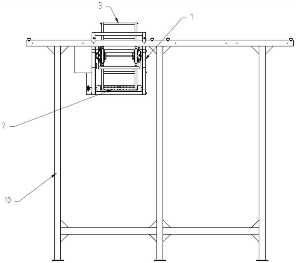
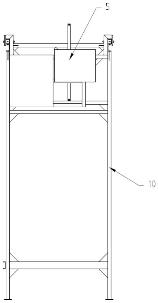
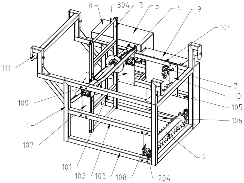
[0045] see Figure 3-Figure 6 , Figure 3-Figure 6 It is a structural schematic diagram of a device for automatically separating and unloading a stack of baskets in this embodiment, including a frame 1, a rotating lifting mechanism 2, a first push rod assembly 3, a second push rod assembly 4, a power drive Assembly 5 and intermediate transmission assembly 6.

[0046] The power drive assembly 5 is arranged at the rear of the frame 1, and includes a motor 501, the output end of which is connected to a first rotating shaft 504, and the first rotating shaft 504 passes through the first push rod assembly 3 and the second push rod assembly 3. The push rod assembly 4 is then connected to the frame 1, wherein the second push rod assembly 4 is fixedly connected to the first rotation shaft 504, and the first push rod assembly 3 is rotatably connected to the first rotation shaft 504, An elastic member is connected between the first push rod assembly 4 and the second push rod assembly 5...


PUM


Abstract

The invention provides equipment for automatically separating and unloading stacked basket bodies. The equipment comprises a rack, a rotary hoisting mechanism, a first pushing rod assembly, a second pushing rod assembly, a power drive assembly and a middle transmission assembly. A motor output end of the power drive assembly is connected with a first rotating shaft. The first rotating shaft penetrates through the first pushing rod assembly and the second pushing rod assembly. The second pushing rod assembly is fixedly connected to the first rotating shaft. The first pushing rod assembly is connected to the first rotating shaft in a rotating manner. An elastic part is connected between the first pushing rod assembly and the second pushing rod assembly. The power drive assembly transmits power to the rotary hoisting mechanism through the middle transmission assembly. The rotary hoisting mechanism and the first pushing rod assembly cooperate to push out the basket bodies to a conveying belt. According to the equipment, the basket bodies are sequentially pushed from the top, pushing rods are not directly connected with a motor, an elastic pushing manner is adopted, thus damage to the basket bodies is avoided, and the equipment is high in efficiency, high in practicality and small in occupied area.

Description

technical field [0001] The invention relates to the technical field of poultry processing, in particular to a device for automatically separating and unloading a stack of baskets. Background technique [0002] At present, on the production line of the poultry processing workshop, chickens and ducks are transported by special baskets. Generally, stacks of duck baskets are automatically transported to a high place through lifting equipment, and then manually transported to the conveyor belt one by one. The working environment on site is harsh, and workers The work intensity is high and the working hours are long. There is a separating device in the prior art, which can lift up all the duck baskets in a stack except the bottom one, then push out the bottom duck baskets, and then put down the bottom duck baskets one by one to realize the automatic separation of the stacked baskets , but this kind of method of separating duck baskets from the bottom requires more auxiliary equip...

Claims


Application Information

Patent Timeline
Patent Type & Authority Applications(China)
IPC IPC(8): B65G47/82B65G67/24
CPCB65G47/82B65G67/24
Inventor 李开亮万光金
Owner JIANGSU DEEPAGRI INTELLIGENT TECH CO LTD
Learn More