Plug-pull type top-end-driving electric sliding door mechanism and driving method

A sliding door and plug-type technology, which is applied to the power control mechanism, wing leaf control mechanism, doors, etc., can solve the problems that do not meet the motion design of the sliding door of the car, and achieve low noise, good stability and stability Good results

Active Publication Date: 2020-11-13
WUHU MOTIONTEC AUTOMOTIVE
10 Cites 3 Cited by

AI-Extracted Technical Summary

Problems solved by technology

The current traditional sliding door motion trajectory does not meet the emerging motion design of auto...

Abstract

The invention provides a plug-pull type top-end-driving electric sliding door mechanism and a driving method. A motor is started, the motor drives a belt to move, the belt is in engaged connection with a rotating gear through a guide wheel, the rotating gear at the bottom of a middle sliding block is driven to move, then the middle sliding block is driven to move, the middle sliding block drives aside sliding block to move, the middle sliding block is inserted into a bent upper guide rail through a guide block at the bottom, then the middle sliding block moves along a track of the upper guiderail, and then a vehicle door moves along the track of the upper guide rail to be opened; when the vehicle door is opened, the acting force of outward movement of a lower guide rail drives a swing arm outwards, so that the swing arm pulls the lower guide rail outwards; when the vehicle door is closed, a vehicle body mounting limiting block on the right side limits the right end of the lower guiderail; and by means of the structure of the upper guide rail and the lower guide rail, stability is good, noise is low, stability is good, the running track of the belt is corrected through the guidewheels at an alternating position, and double-composite movement of Y-direction movement and X-direction movement can be achieved.

Application Domain

Power-operated mechanismWing suspension devices +1

Technology Topic

Electric machineryCar door +5

Image

  • Plug-pull type top-end-driving electric sliding door mechanism and driving method
  • Plug-pull type top-end-driving electric sliding door mechanism and driving method
  • Plug-pull type top-end-driving electric sliding door mechanism and driving method

Examples

  • Experimental program(1)

Example Embodiment

[0013] In order to deepen the understanding of the present invention, the present invention will be described in further detail below in conjunction with examples. The examples are only used to explain the present invention and do not constitute a limitation on the protection scope of the present invention.
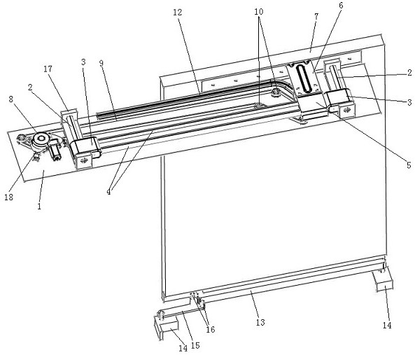
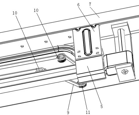
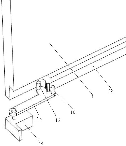
[0014] Such as Figure 1-3 As shown, this embodiment provides a plug-type top-drive electric sliding door mechanism, which includes a mounting top plate 1 on the vehicle body. The top of the mounting top plate 1 is provided with two left and right short sliding rods 2 that slide inside and outside. The rod 2 is covered with side sliders 3, and the left and right side sliders 3 are jointly provided with two long sliders 4 inside and outside for connection. The long slider 4 and the short slider 2 are set at 90°; two long sliders 4 is covered with a middle sliding block 5, the outside of the middle sliding block 5 is connected with a door mounting bracket 6, and the outside of the door mounting bracket 6 is connected with a door 7. The door 7 is located on the outer side of the mounting top plate 1 and extends downward; The motor 8, the motor 8 is connected with an endless belt 9; the top of the mounting top plate 1 is provided with two inner and outer guide wheels 10, the bottom of the middle slider 5 is provided with a rotating gear 11, and the belt 9 comes out of the motor and sequentially engages through the outer guide wheels 10 and rotates The gear 11 and the inner guide wheel 10 finally return to the motor to mesh with the motor gear to form a ring shape. The slider 5 is driven by the motor to move; the top of the mounting top plate 1 is provided with a bent upper rail 12 near the outside. A guide block is provided at the bottom of the sliding block 5, which is inserted into the upper guide rail 12 to guide; the outer end of the upper guide rail 12 is linearly and horizontally attached to the outer side of the mounting top plate 1, and the right part of the upper guide rail 12 is bent inward.
[0015] The bottom of the door 7 is provided with a lower rail 13, and the left and right sides of the lower rail 13 are provided with body mounting limit blocks 14, which limit the left and right ends when the door 7 is closed; the top of the body mounting limit block 14 on the left is movably connected with The swing arm 15 is provided with two inner and outer pulleys 16 at the top right end of the swing arm 15. The left end of the lower rail 13 is a concave arc. When the door 7 is closed, the outer pulley 16 is located at the arc, and the inner pulley 16 is located below On the inner side of the guide rail 14, when the door is opened, the lower guide rail 13 moves outward, and the outer pulley 16 moves along the arc to the inner side of the lower guide rail 13, driving the swing arm to move outward, and the swing arm pulls out the lower rail. The two pulleys 16 are attached to the inner side of the lower rail 13 to limit the position while moving.
[0016] The inner and outer ends of the short sliding rod 2 are provided with short sliding rod mounting seats 17 for mounting on the mounting top plate 1; the bottom of the motor 8 is provided with a motor bracket 18 for mounting on the mounting top plate 1.
[0017] This embodiment also provides a method for driving the electric sliding door mechanism with a plug-type top drive. First, the motor is started, the motor drives the belt to move, and the belt drives the rotating gear at the bottom of the middle slide to move, thereby driving the middle slide to move. The block drives the side slider to move. The middle slider is inserted into the bent upper rail through the guide block at the bottom, so that the middle slider moves along the track of the upper rail, and the door opens along the track of the upper rail; When the door is opened, the force of the downward movement of the lower rail drives the swing arm outward, so that the swing arm pulls the lower rail outward, and at the same time, the two pulleys on the lower swing arm fit the lower rail to fix the lower part of the door. Stability: When the door is closed, the body-mounted limit block on the right limits the right end of the lower rail.
[0018] Through the structure of the upper and lower guide rails, the above embodiments have good stability, low noise and good stability. In the alternating position, there are guide wheels to correct the running trajectory of the belt, and the double compound of Y-direction movement and X-direction movement can be realized. movement.

PUM

no PUM

Description & Claims & Application Information

We can also present the details of the Description, Claims and Application information to help users get a comprehensive understanding of the technical details of the patent, such as background art, summary of invention, brief description of drawings, description of embodiments, and other original content. On the other hand, users can also determine the specific scope of protection of the technology through the list of claims; as well as understand the changes in the life cycle of the technology with the presentation of the patent timeline. Login to view more.

Similar technology patents

Novel methods of treating neutorpenia using g-csf protein complex

PendingUS20210008166A1easily administerstable
Owner:HANMI PHARMA +1

DNA detection method based on rapid nanogold aggregation induced by nucleic acid dye

PendingCN110568175AFast aggregationstable
Owner:CHENGDU UNIVERSITY OF TECHNOLOGY

Round steel pipe supporting structure

InactiveCN103015527AIncreased torsional stiffnessstable
Owner:SHANDONG HANGXIAO STEEL STRUCTURE CO LTD

Autorotation type wood peeling machine with wood chip collecting function

InactiveCN112277116AImprove the use effectstable
Owner:德清天木坊装饰材料有限公司

Classification and recommendation of technical efficacy words

  • stable
  • reduce noise

Liver subsection method based on CT image and system thereof

InactiveCN101425186Areduce noiseavoid blur
Owner:HUAZHONG UNIV OF SCI & TECH

Noise reduction device

ActiveUS20100014683A1reduce noisehigh quality
Owner:PANASONIC CORP

Automatic image capture

ActiveUS20110170740A1reduce noiseenhance edge
Owner:NORTHWEST IP LLC +1

Shift register electrode, grid electrode driver, array substrate and display device

InactiveCN102654986AReduced Threshold Voltage Driftreduce noise
Owner:BOE TECH GRP CO LTD +1
Why Eureka
Try Eureka