Equipment capable of reducing waterflow potential energy and generating power efficiently

A technology of water flow potential energy and equipment, applied in the directions of hydropower generation, mechanical equipment, engine control, etc., can solve the problems of adverse effects of downstream people and low power generation, and achieve the effect of reducing water flow potential energy, increasing power generation, and speeding up rotation speed.

Inactive Publication Date: 2020-11-13
福州侠维怡电子科技有限公司
View PDF0 Cites 0 Cited by
  • Summary
  • Abstract
  • Description
  • Claims
  • Application Information

AI Technical Summary

Problems solved by technology

[0002] At present, with the development of society, the utilization of energy continues to develop. Among them, hydropower generation is an environmentally friendly and sustainable energy utilization method. The basic principle of hydropower generation is to use the water level drop and cooperate with the hydroelectric generator to generate electricity, that is, to use water. The potential energy is converted into the mechanical energy of the water wheel, and then the mechanical energy is used to drive the generator to obtain electricity. However, the existing power generation method can only make one of the stator and rotor of the generator rotate to generate electricity. The power generation is not high, and the water flow continues after power generation. Flow in which the energy is such that the water rushes downstream, potentially adversely affecting people downstream

Method used


Image

  • Equipment capable of reducing waterflow potential energy and generating power efficiently
  • Equipment capable of reducing waterflow potential energy and generating power efficiently
  • Equipment capable of reducing waterflow potential energy and generating power efficiently

Examples


Embodiment Construction

[0014] All features disclosed in this specification, or steps in all methods or processes disclosed, can be combined in any way, except for mutually exclusive features and or steps.

[0015] Combine below Figure 1-4 The present invention is described in detail, and for convenience of description, the orientations mentioned below are now stipulated as follows: figure 1 The up, down, left, right, front and back directions of the projection relationship itself are the same.

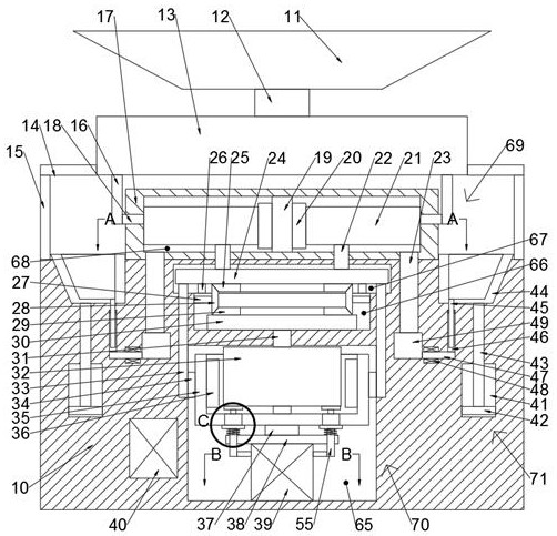
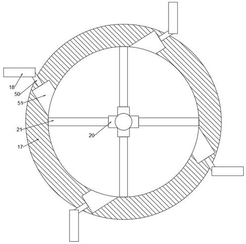
[0016] A device for reducing the potential energy of water flow and generating electricity efficiently in the device of the present invention includes a machine body 10, a power generation chamber 65 is arranged in the body 10, a reverse chamber 66 is provided on the upper side of the power generation chamber 65, and the reverse chamber 66 The upper side is provided with a rotating chamber 67, the upper side of the body 10 is fixed with a rotating body 17, the rotating body 17 is provided with a power cham...


PUM


Abstract

The invention discloses equipment capable of reducing waterflow potential energy and generating power efficiently. The equipment comprises an equipment body, wherein a power generation cavity is formed in the equipment body, a reversing cavity is formed in the upper side of the power generation cavity, a rotating cavity is formed in the upper side of the reversing cavity, a rotating body is fixedly arranged on the upper side surface of the equipment body, a power cavity is formed in the rotating body, a power device for supplying power by a hydraulic power is arranged on the upper side of theequipment body and comprises two supporting rods fixedly mounted on the upper side surface of the equipment body, a supporting plate is fixedly arranged on the two supporting rods, a water storage pool is fixedly arranged in the supporting plate, a communicating water delivery pipe is fixedly arranged on the upper side of the water storage pool, a water inlet is fixedly arranged on the upper sideof the water delivery pipe, a power generating device for generating power rotationally is arranged on the lower side of the equipment body, and draining devices capable of reducing waterflow energy are arranged on the left and right sides of the equipment body. The equipment can generate power by the waterflow, increases power generating capacity, can control to reduce energy of the waterflow andprevents too large waterflow impact during draining.

Description

technical field [0001] The invention relates to the related field of hydroelectric power generation equipment, in particular to equipment for reducing the potential energy of water flow and generating electricity efficiently. Background technique [0002] At present, with the development of society, the utilization of energy continues to develop. Among them, hydropower generation is an environmentally friendly and sustainable energy utilization method. The basic principle of hydropower generation is to use the water level drop and cooperate with the hydroelectric generator to generate electricity, that is, to use water. The potential energy is converted into the mechanical energy of the water wheel, and then the mechanical energy is used to drive the generator to obtain electricity. However, the existing power generation method can only make one of the stator and rotor of the generator rotate to generate electricity. The power generation is not high, and the water flow contin...

Claims


Application Information

Patent Timeline
Patent Type & Authority Applications(China)
IPC IPC(8): F03B13/00F03B15/06
CPCF03B13/00F03B15/06F05B2220/706F05B2270/3013Y02E10/20
Inventor 周国杰
Owner 福州侠维怡电子科技有限公司
Why Eureka
Try Eureka