Novel adjustable eddy current displacement sensor mounting bracket and adjusting method
A technology of eddy current sensors and displacement sensors, which is applied in the direction of adopting electrical devices, instruments, measuring devices, etc., can solve the problems of single support, low accuracy and reliability, achieve high-efficiency adjustment, improve safety and work efficiency, and low cost Effect
- Summary
- Abstract
- Description
- Claims
- Application Information
AI Technical Summary
Problems solved by technology
Method used
Image

Examples
specific Embodiment approach 1
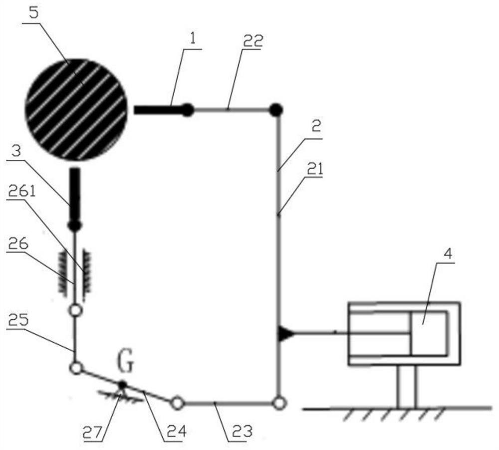
[0031] Specific implementation mode one: combine Figure 1-Figure 4 Describe this embodiment, a new type of adjustable eddy current displacement sensor mounting bracket in this embodiment, including a horizontal eddy current sensor 1, an adjustment bracket 2, a vertical eddy current displacement sensor 3 and a hydraulic cylinder 4, the cylinder body of the hydraulic cylinder 4 The end is fixed on the ground, the output end of the hydraulic cylinder 4 is fixedly connected to one end of the adjustment bracket 2, and the other end of the adjustment bracket 2 is respectively installed with a horizontal eddy current sensor 1 and a vertical eddy current displacement sensor 3, and the horizontal eddy current sensor 1 is arranged on the In the horizontal direction close to the rotating shaft 5, the vertical eddy current displacement sensor 3 is arranged in the vertical direction close to the rotating shaft 5, and the hydraulic cylinder 4 is electrically connected to the control system,...
specific Embodiment approach 2
[0032] Specific implementation mode two: combination Figure 1-Figure 4 Describe this embodiment, based on specific embodiment 1, a new type of adjustable eddy current displacement sensor mounting bracket in this embodiment, the adjustment bracket 2 includes a thrust plate 21, a horizontal rod 22, a second connecting rod 23, and a steering rod 24 , the first connecting rod 25, the guide rod 26 and the limit seat 27, the output end of the hydraulic cylinder 4 is fixedly connected and installed on one side of the thrust plate 21, and one end of the thrust plate 21 is fixedly installed with a horizontal rod 22, and the other end of the horizontal rod 22 is fixedly installed There is a horizontal eddy current sensor 1, the other end of the thrust plate 21 is hingedly installed with one end of the second connecting rod 23, the other end of the second connecting rod 23 is hingedly installed with one end of the steering rod 24, and the middle part of the steering rod 24 is hingedly in...
specific Embodiment approach 3
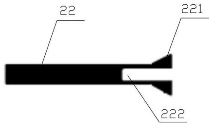
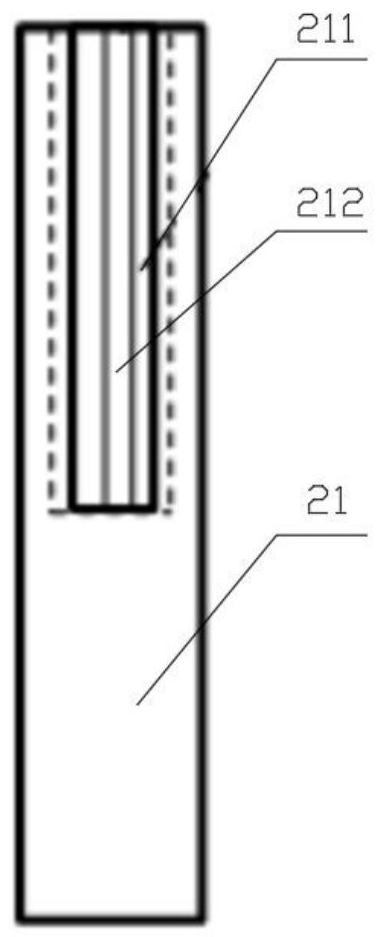
[0033] Specific implementation mode three: combination Figure 1-Figure 4 Describe this embodiment, a new type of adjustable eddy current displacement sensor mounting bracket in this embodiment, one end of the horizontal rod 22 is processed with a dovetail platform 221 and a threaded hole 222, and the upper end of the thrust plate 21 is processed with a dovetail groove 211 and a bolt interface 212 , the dovetail platform 221 on the horizontal rod 22 is installed in the dovetail groove 211 on the thrust plate 21 with clearance fit, and the bolts are fixedly connected and installed on the threaded holes 222 of the horizontal rod 22 through the bolt interface 212 on the thrust plate 21, so that vertical For the adjustment of the direction, the dovetail platform 221 and the dovetail groove 211 play the role of clamping and limiting, so as to ensure that the horizontal eddy current sensor 1 is always perpendicular to the maximum radius of the rotating shaft 5 .
PUM
 Abstract
Description
Claims
Application Information
 - R&D
- Intellectual Property
- Life Sciences
- Materials
- Tech Scout
- Unparalleled Data Quality
- Higher Quality Content
- 60% Fewer Hallucinations
Browse by: Latest US Patents, China's latest patents, Technical Efficacy Thesaurus, Application Domain, Technology Topic, Popular Technical Reports.
© 2025 PatSnap. All rights reserved.Legal|Privacy policy|Modern Slavery Act Transparency Statement|Sitemap|About US| Contact US: help@patsnap.com