Laser radar inertial navigation odometer considering dynamic obstacles and mapping method and system

A dynamic obstacle and laser radar technology, applied in the field of AB testing, can solve difficult problems such as low drift robust pose estimation

Active Publication Date: 2020-11-13
BEIJING UNIV OF CIVIL ENG & ARCHITECTURE
View PDF18 Cites 38 Cited by
  • Summary
  • Abstract
  • Description
  • Claims
  • Application Information

AI Technical Summary

Problems solved by technology

However, since the above methods all assume that the surrounding environment is static and do not take into account the impact of dynamic obstacles on pose estimation and mapping, it is difficult for these methods to achieve low-drift, robust pose estimation in outdoor dynamic road environments

Method used


Image

  • Laser radar inertial navigation odometer considering dynamic obstacles and mapping method and system
  • Laser radar inertial navigation odometer considering dynamic obstacles and mapping method and system
  • Laser radar inertial navigation odometer considering dynamic obstacles and mapping method and system

Examples


Embodiment 1

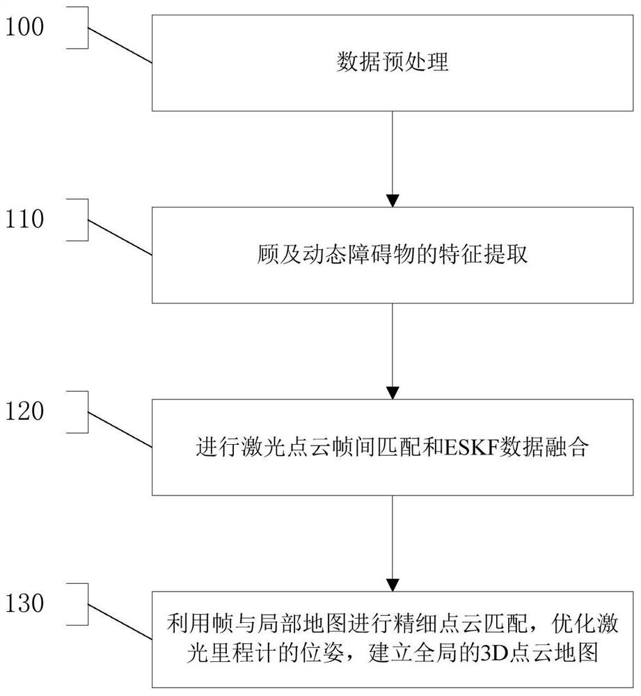
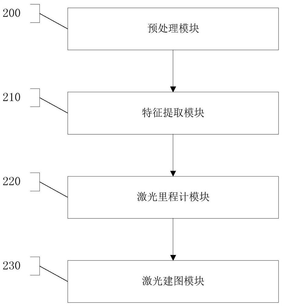
[0080] Such as figure 1 , 2 As shown, step 100 is executed, the preprocessing module 200 performs data preprocessing, and performs distortion compensation and correction on all laser point clouds in each frame through high-frequency MEMS inertial navigation assisted lidar.

[0081] The method for distortion compensation correction includes the following sub-steps:

[0082] Step 01: First find the time stamp t with the current laser point curr closest timestamp t k and t k+1 The continuous inertial navigation measurement value of ;

[0083] Step 02: Through the inertial navigation integration process, respectively obtain the state of the inertial navigation system in the world coordinate system W at time k and time k+1, the formula is:

[0084]

[0085]

[0086] Among them, p represents the position, v represents the velocity, θ represents the angular vector, x represents the orientation of the x-axis, y represents the orientation of the y-axis, and z represents the ...

Embodiment 2

[0132] The present invention improves on the basis of LOAM and Lego-LOAM schemes, focusing on improving their feature extraction and laser odometer parts, mainly including the following three aspects:


PUM


Abstract

The invention provides a laser radar inertial navigation odometer considering a dynamic obstacle and a mapping method and system, and the method comprises the steps: data preprocessing, and also comprises the following steps: the features of the dynamic obstacle are extracted; laser point cloud inter-frame matching and ESKF data fusion are carried out; and fine point cloud matching is carried outby using the frame and a local map, the pose of the laser odometer is optimized, and a global 3D point cloud map is established. The invention provides a laser radar inertial navigation odometer considering dynamic obstacles and a mapping method and system. Dynamic obstacles in a road environment are removed by adopting a depth image mode, schemes are different, point cloud matching and pose solving are carried out step by step by adopting three feature point clouds in a classified mode, and pose estimation precision is improved by utilizing an ESKF framework to fuse pre-integration information of inertial navigation and laser radar inter-frame matching information.

Description

technical field [0001] The invention relates to the technical field of AB testing, in particular to a laser radar inertial navigation odometer and mapping method and system considering dynamic obstacles. Background technique [0002] Accurate pose estimation is the key technology for mobile robot positioning and navigation. It can calculate the position and attitude information of the robot, and provide an important guarantee for the real-time control, decision-making and path planning of the robot. [0003] SLAM technology can realize the self-motion estimation of mobile robots in an unknown environment, that is, "positioning", and at the same time establish a map of the surrounding environment. According to the different sensors, SLAM technology can be roughly divided into two categories: laser SLAM and visual SLAM [1]. The SLAM technology based on 3D lidar does not require GNSS signals, can directly obtain spatial three-dimensional information, is not affected by illumin...

Claims


Application Information

Patent Timeline
Patent Type & Authority Applications(China)
IPC IPC(8): G01S17/86G01S17/894G01C21/32
CPCG01S17/86G01S17/894G01C21/32Y02T10/40
Inventor 危双丰庞帆
Owner BEIJING UNIV OF CIVIL ENG & ARCHITECTURE
Why Eureka
Try Eureka