Engineering field safety monitoring method based on RTK technology

An engineering and on-site technology, which is applied in the direction of location information-based services, detection/exploration using thermal methods, instruments, etc., can solve the problems of low efficiency, time-consuming and labor-intensive safety inspections on the engineering site, and achieve the effect of improving accuracy and efficiency

Pending Publication Date: 2020-11-13
STATE GRID ZHEJIANG ELECTRIC POWER +1
View PDF0 Cites 2 Cited by
  • Summary
  • Abstract
  • Description
  • Claims
  • Application Information

AI Technical Summary

Problems solved by technology

[0003] Usually, manual inspection is used to inspect and manage the project site. With this method, it is possible to check whether the equipment and personnel on the

Method used


Image

  • Engineering field safety monitoring method based on RTK technology
  • Engineering field safety monitoring method based on RTK technology
  • Engineering field safety monitoring method based on RTK technology

Examples


Embodiment 1

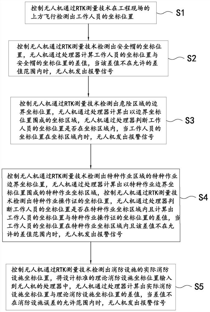
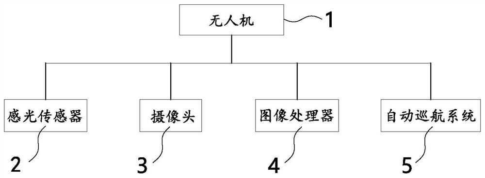
[0029] Such as figure 1 and figure 2 As shown, the preferred structure of the monitoring method of engineering site safety based on RTK technology in this embodiment includes:

[0030] Step 1S1: Control the unmanned aerial vehicle 1 to detect the coordinate position of the staff by flying above the engineering site through RTK measurement technology;

[0031] Step 2S2: Control UAV 1 to detect the coordinate position of the helmet through RTK measurement technology, UAV 1 calculates the difference between the coordinate position of the staff and the coordinate position of the helmet through the processor, when the difference is not within the allowable When within the difference range, the UAV 1 sends out an alarm signal;

[0032] Step 3S3: Control UAV 1 to detect the boundary coordinate position of the dangerous area through RTK measurement technology, UAV 1 calculates the coordinate area surrounded by the boundary coordinate position through the processor, and UAV 1 judges...

Embodiment 2

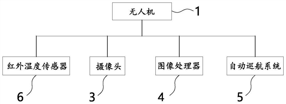
[0048] The difference between this embodiment and Embodiment 1 is that, if image 3 As shown, in this embodiment, the staff carry a first heating element, and the drone 1 is provided with an infrared temperature sensor 6, and the drone 1 works by identifying the position of the first heating element through the infrared temperature sensor 6. The coordinate position of the personnel, the safety helmet is provided with a second heating element, and the UAV 1 identifies the coordinate position of the safety helmet by identifying the position of the second heating element through the infrared temperature sensor 6. With this structure, the UAV 1 The position of the staff and the safety helmet can be located by the infrared temperature sensor 6, and this embodiment can also achieve the technical effect of the first embodiment.


PUM


Abstract

The invention provides an engineering field safety monitoring method based on an RTK technology, and belongs to the technical field of power transmission. According to the method, an unmanned aerial vehicle is controlled to fly above an engineering site through an RTK measurement technology to detect the coordinate position of a worker, the coordinate position of a safety helmet, the boundary coordinate position of a dangerous area, the special operation boundary coordinate position of a special operation area and the actual fire-fighting facility coordinate position of a fire-fighting facility, and a processor of the unmanned aerial vehicle compares the coordinate position of the worker with the coordinate position of the safety helmet, the boundary coordinate position of the dangerous area, the special operation boundary coordinate position of the special operation area and the actual fire-fighting facility coordinate position of the fire-fighting facility to monitor the safety of the engineering site. The safety monitoring method has the advantages that the safety inspection efficiency of the engineering site can be improved by adopting the structure, and the safety monitoring method is used for monitoring the safety of the engineering site.

Description

【Technical field】 [0001] The invention relates to an engineering site safety monitoring method based on RTK technology, which belongs to the technical field of electric power transmission. 【Background technique】 [0002] With the continuous advancement of the urbanization process, the construction industry is developing rapidly, and there are more and more construction projects, making the construction more and more difficult and dangerous. Therefore, personnel are required to regularly inspect and manage during the project construction process. [0003] Manual inspection is usually used to inspect and manage the project site. Using this method, it is possible to check whether the equipment and personnel on the project site meet the safety regulations. However, this method is time-consuming and laborious, making the safety inspection efficiency of the project site low. 【Content of invention】 [0004] The technical problem to be solved by the present invention is to provid...

Claims


Application Information

Patent Timeline
IPC IPC(8): G01S19/41G01V9/00G08B21/02G08B21/18H04W4/021
CPCG01S19/41G01V9/005G08B21/02G08B21/18H04W4/021
Inventor 钟晓波姚耀明陈钢陈哲傅旭华秦沈峰邵荐陈茂锐袁琪
Owner STATE GRID ZHEJIANG ELECTRIC POWER
Why Eureka
Try Eureka