
Device for mounting motor magnets of camera

A technology for installing devices and cameras, which is applied in the direction of electromechanical devices, magnets, magnetic objects, etc., and can solve problems such as magnet misalignment

Active Publication Date: 2020-11-13
湖南新视电子技术有限公司
View PDF6 Cites 1 Cited by
  • Summary
  • Abstract
  • Description
  • Claims
  • Application Information

AI Technical Summary

Problems solved by technology

The traditional method of motor magnet installation is a single-layer installation. After the bottom layer is installed, the upper layer is installed. Two devices and two operators are required for two installations, and defects such as magnet misalignment are prone to occur.

Method used


Image

  • Device for mounting motor magnets of camera
  • Device for mounting motor magnets of camera
  • Device for mounting motor magnets of camera

Examples


Embodiment Construction

[0033] The following will clearly and completely describe the technical solutions in the embodiments of the present invention with reference to the accompanying drawings in the embodiments of the present invention. Obviously, the described embodiments are only some of the embodiments of the present invention, not all of them. Based on the embodiments of the present invention, all other embodiments obtained by persons of ordinary skill in the art without creative efforts fall within the protection scope of the present invention.

[0034] It should be noted that all directional indications (such as up, down, left, right, front, back...) in the embodiments of the present invention are only used to explain the relationship between the components in a certain posture (as shown in the accompanying drawings). Relative positional relationship, movement conditions, etc., if the specific posture changes, the directional indication will also change accordingly.

[0035] In addition, in t...


PUM


Abstract

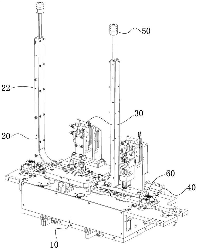
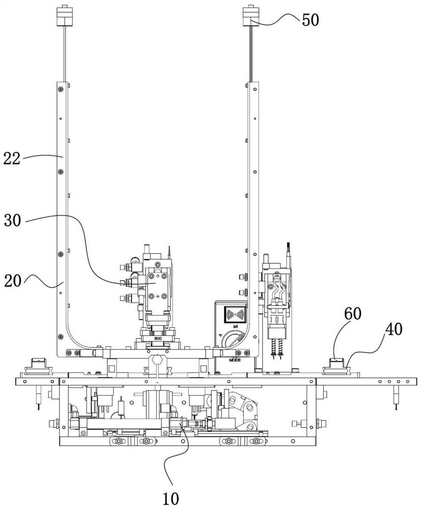
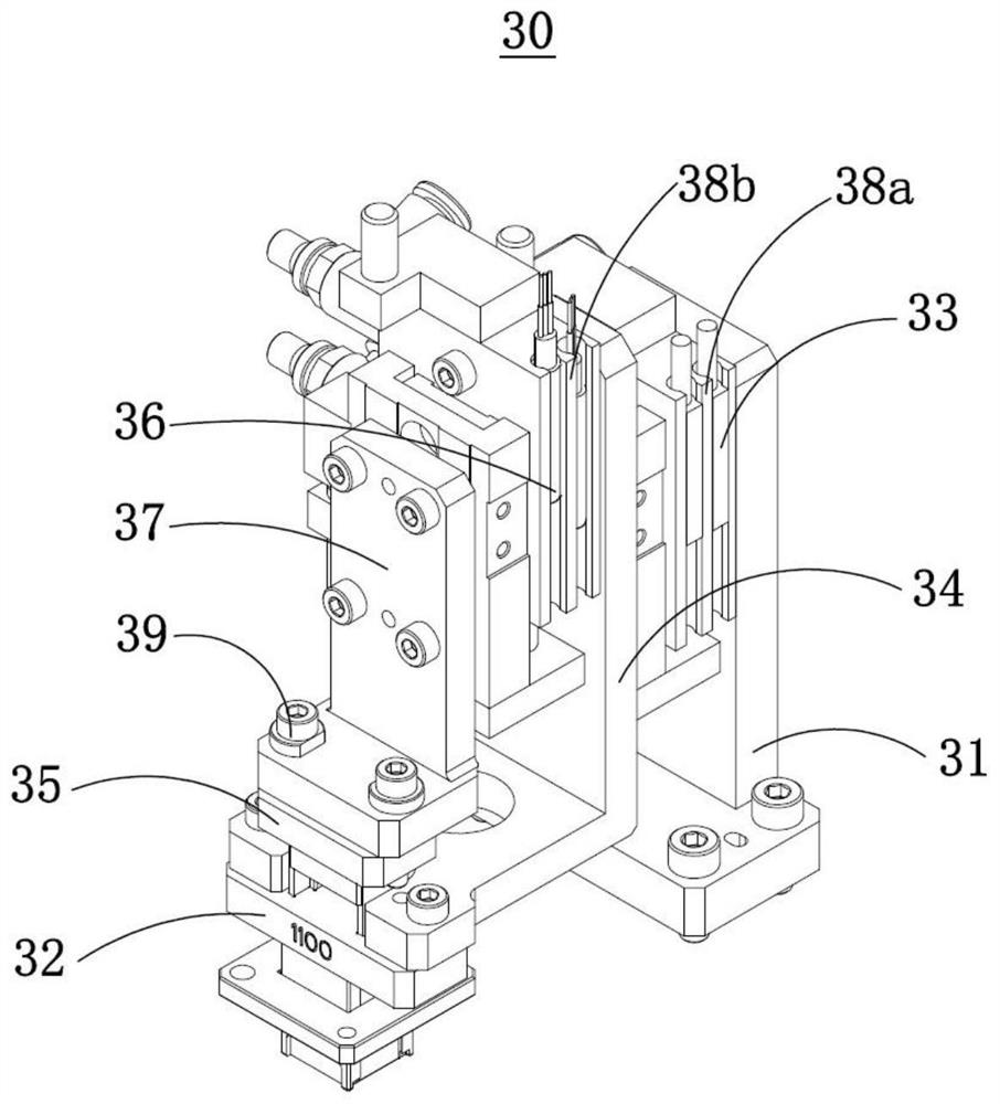
The invention discloses a device for mounting motor magnets of a camera. The device comprises a machine table, a magnet feeding mechanism, a magnet mounting mechanism and a clamp conveying mechanism,wherein the magnet feeding mechanism comprises a feeding bottom plate and two feeding slideways, the feeding bottom plate is fixed to the machine table, the two feeding slideways are arranged at the two ends of the feeding bottom plate in a bilateral symmetry mode respectively, the feeding slideways are used for containing two rows of strip-shaped magnets arranged side by side, and a through holeis formed in the center of the feeding bottom plate; the magnet mounting mechanism comprises a fixing support, a punching core, a punching core air cylinder, a punching core support, a punching claw,a punching claw air cylinder and a punching claw support, the punching claw is arranged on the peripheral side of the punching core in a sleeving mode, and the size of the punching claw is matched with that of the through hole so as to enable the punching claw to penetrate through the through hole. According to the device for mounting the motor magnets of the camera provided by the invention, theupper and lower layers of magnets can be mounted at the same time, equivalently, the work of two existing devices is completed at a time, the equipment acquisition cost is reduced, and the labor costis saved; and the stacking precision of the two layers of magnets is high, and the product quality is improved.

Description

technical field [0001] The invention relates to the technical field of precision manufacturing, in particular to a device for installing a camera motor magnet. Background technique [0002] With the rapid development of science and technology and market demand, mobile phones have become a necessity in our lives, and the competition among mobile phone brands is becoming increasingly fierce. Nowadays, a very important direction of mobile phone competition is the quantity and quality of mobile phone cameras. As one of the basic components of the camera motor in mobile phones, the installation efficiency and assembly quality of magnets have become an important aspect of development. The traditional method of motor magnet installation is a single-layer installation. After the bottom layer is installed, the upper layer is installed. The two installations require two equipment and two operators, and are prone to defects such as magnet misalignment. Contents of the invention [0...

Claims


Application Information

Patent Timeline
IPC IPC(8): H02K15/02H02K15/03B23P19/00B23P19/027H01F7/00
CPCB23P19/001B23P19/027H01F7/00H02K15/02H02K15/03
Inventor 付湘华肖畅周晖
Owner 湖南新视电子技术有限公司
Learn More