
Image processing method and device, electronic equipment and computer readable medium

A processing method and technology of camera devices, applied in the field of image processing, can solve problems such as poor user experience, optical axis error, and inconsistent observation directions of two cameras

Active Publication Date: 2020-11-13
MEGVII BEIJINGTECH CO LTD
View PDF9 Cites 4 Cited by
  • Summary
  • Abstract
  • Description
  • Claims
  • Application Information

AI Technical Summary

Problems solved by technology

But in fact, as far as the focal length is concerned, each camera device has a certain error during assembly, and its actual focal length is also different from the theoretical reference value given by the lens manufacturer; as for the optical axis, the two camera devices assembled in When they are together, the optical axes will also produce errors instead of being absolutely parallel, resulting in incomplete observation directions of the two cameras, which will lead to poor user experience when switching cameras

Method used


Image

  • Image processing method and device, electronic equipment and computer readable medium
  • Image processing method and device, electronic equipment and computer readable medium
  • Image processing method and device, electronic equipment and computer readable medium

Examples


Embodiment 1

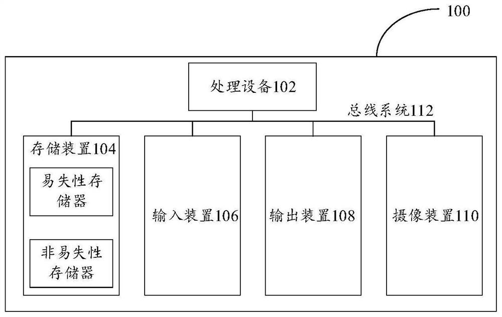
[0035] First, refer to figure 1 The electronic device 100 for implementing the embodiments of the present invention will be described, and the electronic device can be used to run the image processing methods of the various embodiments of the present invention.

[0036] Such as figure 1 As shown, the electronic device 100 includes one or more processing devices 102, one or more storage devices 104, an input device 106, an output device 108, and a camera device 110, and these components are connected through a bus system 112 and / or other forms ( not shown) interconnection. It should be noted that figure 1 The components and structure of the electronic device 100 shown are only exemplary, not limiting, and the electronic device may also have other components and structures as required.

[0037] The processing device 102 may be a central processing unit (CPU) or other form of processing unit having data processing capabilities and / or instruction execution capabilities, and may...

Embodiment 2

[0070] According to an embodiment of the present invention, an embodiment of an image processing method is provided. It should be noted that the steps shown in the flowcharts of the accompanying drawings can be executed in a computer system such as a set of computer-executable instructions, and, Although a logical order is shown in the flowcharts, in some cases the steps shown or described may be performed in an order different from that shown or described herein.

[0071] Figure 6 is a flowchart of an image processing method according to an embodiment of the present invention, such as Figure 6 As shown, the method includes the following steps:

[0072] Step S602, acquiring a first image captured by the first camera device; and determining a target ROI area in the first image.

[0073] In this application, the first camera device here and the second camera device described in the following steps are camera devices in a mobile terminal (for example, a mobile phone), wherein...

Embodiment 3

[0163] The embodiment of the present invention also provides an image processing device, the image processing device is mainly used to execute the image processing method provided in the above content of the embodiment of the present invention, the image processing device provided in the embodiment of the present invention is described in detail below introduce.

[0164] Figure 10 is a schematic diagram of an image processing device according to an embodiment of the present invention, such as Figure 10 As shown, the image processing device mainly includes: a first acquisition unit 10, a calculation unit 20, a second acquisition unit 30, a slice processing unit 40, an image correction unit 50 and a switching display unit 60, wherein:

[0165] A first acquiring unit, configured to acquire a first image captured by the first camera device; and determine a target ROI area in the first image;

[0166] A calculation unit, configured to calculate the ROI offset of the target ROI ...


PUM


Abstract

The invention provides an image processing method and device, electronic equipment and a computer readable medium, and relates to the technical field of image processing. The method comprises the steps: obtaining a first image collected by a first camera device; determining a target ROI region in the first image; calculating the ROI offset of the target ROI in the first image and the second image;acquiring a current magnification of the first image, and slicing the ROI offset according to the current magnification to obtain a current superposition offset for performing image stereo correctionon the first image at the current moment; performing image three-dimensional correction on the first image based on the current superposition offset to obtain a corrected first image; if the currentmagnification is the preset switching magnification, switching the mobile terminal from the first camera device to the second camera device for display,. The technical problem that in the prior art, when imaging switching of the camera devices is conducted, hopping is obvious is solved.

Description

technical field [0001] The present invention relates to the technical field of image processing, in particular to an image processing method, device, electronic equipment and computer readable medium. Background technique [0002] For a mobile terminal, its camera device is usually a fixed-focus lens, which can only achieve digital zoom. As consumers have higher and higher requirements for functions such as shooting and video recording, in order to solve the defects of digital zoom at high zoom ratios, more and more mobile terminals are equipped with two or more cameras with different focal lengths. The camera devices are matched, for example, one lens FOV (field angle, field angle)=80°, and one lens FOV=40°. At this time, digital zoom and optical zoom can be combined to satisfy consumers. The combination of digital zoom and optical zoom means that one camera device is used to enlarge the image and then switch to another camera device for imaging. The above method is also ...

Claims


Application Information

Patent Timeline
Patent Type & Authority Applications(China)
IPC IPC(8): H04N5/232H04N5/225
CPCH04N23/45H04N23/67H04N23/80H04N23/667H04N23/632
Inventor 刘钦
Owner MEGVII BEIJINGTECH CO LTD
Learn More