Heat exchanger and method for manufacturing such heat exchanger

A heat exchanger and channel technology, applied in the field of heat exchangers, can solve problems such as increased pressure head loss, and achieve the effect of improving efficiency

Active Publication Date: 2020-11-13
INETYX
View PDF10 Cites 0 Cited by
  • Summary
  • Abstract
  • Description
  • Claims
  • Application Information

AI Technical Summary

Problems solved by technology

[0005] These various exchangers, more generally commercially available heat exchangers, generally have a construction that

Method used


Image

  • Heat exchanger and method for manufacturing such heat exchanger
  • Heat exchanger and method for manufacturing such heat exchanger
  • Heat exchanger and method for manufacturing such heat exchanger

Examples


Embodiment Construction

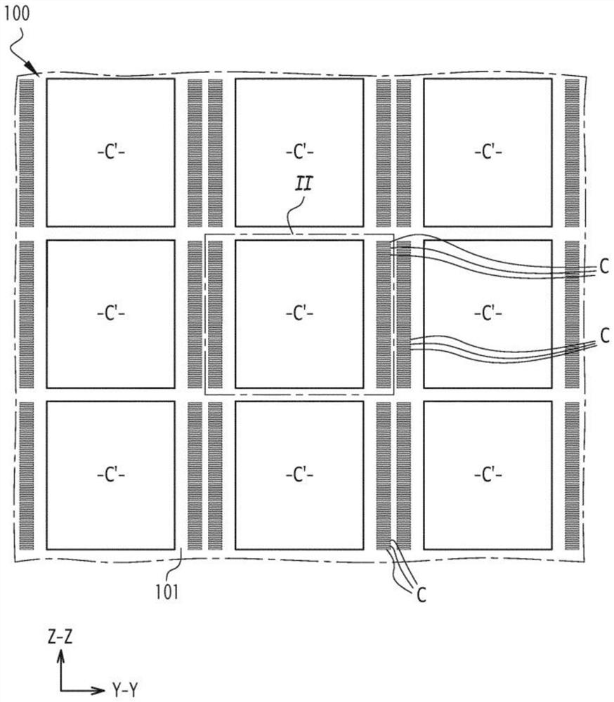
[0036] Figure 1 to Figure 3 A heat exchanger 100 is shown. The exchanger 100 is a recuperator which allows the transfer of thermal energy between a first fluid and a second fluid passing through the body 101 through the body 101 of the exchanger without any mixing between the first fluid and the second fluid .

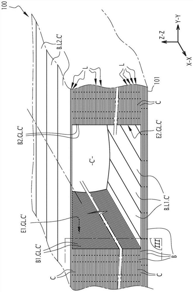
[0037] As outlined below, the body 101 is made of metal and has a three-dimensional shape that will be described with reference to an orthogonal coordinate system having axes labeled X-X, Y-Y and Z-Z, respectively.

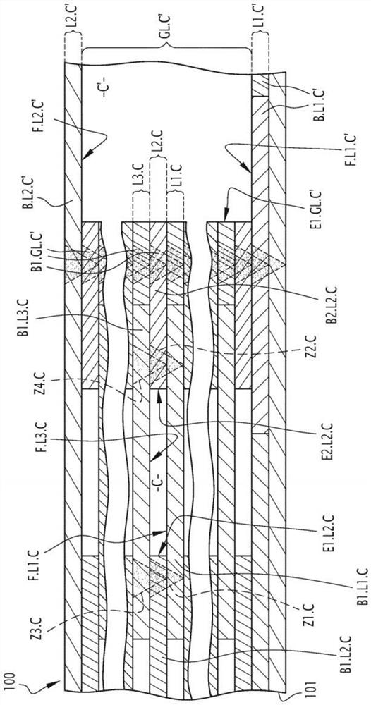
[0038] The exchanger 100 comprises both channels C for the first fluid circulation and channels C' for the second fluid circulation. As described in detail below, the channels C and C', delimited by the main body 101 of the exchanger, extend longitudinally parallel to each other along the axis XX, each of these channels C and C' facing each other along the axis XX with respect to the respective channels of the channel. terminals are connected to each o...


PUM


Abstract

A heat exchanger (100) comprises fluid circulation channels (C) extending lengthwise along a first axis (X-X), and a plurality of layers (L) that are flat and superposed on one another along a secondaxis (Z-Z). In order to improve the performance of this exchanger, each layer is made up of metal strips (B) such that the strips of the one same layer all extend lengthwise in a direction perpendicular to the second axis and adjacent to one another, without necessarily touching, in the plane of the relevant layer. In addition, each of the channels is jointly defined by first, second and third layers, the second layer being intercalated, along the second axis, directly between the first and third layers so that each channel is delimited by a one face of the first layer, one face of the third layer and edges of the second layer which run parallel to the first axis and transversely to the plane of this second layer, these edges being formed by strips of this second layer which are fusion-welded to the first and third layers in fusion zones which extend continuously along the entire length of the channel and which are situated, along a third axis (Y-Y), on either side of the channel.

Description

【Technical field】 [0001] The present invention relates to a heat exchanger. The invention also relates to a method for producing such a heat exchanger. 【Background technique】 [0002] The invention relates to both recuperator type heat exchangers and regenerator type heat exchangers. The main function of a recuperator type heat exchanger is to allow the transfer of thermal energy between a first fluid and a second fluid passing through the exchanger through the walls of the exchanger without any mixing between the two fluids. The two fluids implemented in this context may have different physical and chemical properties. The main function of a heat exchanger of the regenerator type is, on the one hand, to store in its walls the thermal energy provided by the fluid passing through it and, on the other hand, to subsequently return the thermal energy already stored in its walls to the device fluid. [0003] The performance of heat exchangers, whether recuperators or recupera...

Claims


Application Information

Patent Timeline
IPC IPC(8): F28D9/00F28F3/08F28F7/02B21D53/04B23K26/00F28D17/02F28D21/00B23K26/342
CPCF28D9/0062F28D17/02F28D21/0001F28F3/08F28F7/02F28F2270/02F28F2275/06F28F2275/067B23K2101/14B23K2103/12B23K11/0026B23K11/16B23K26/342B23K26/0006B23K11/34B23K26/60B23K26/362B23K26/40B33Y80/00B33Y10/00B23K26/36
Inventor 帕特里克·特勒埃米尔·柯蒂耶
Owner INETYX
Why Eureka
Try Eureka