High-metal soil removing equipment for soil remediation
A soil remediation and high-metal technology, which is applied in the restoration of polluted soil, solid separation, chemical instruments and methods, etc., can solve the problems of complicated operation and inability to remove heavy metals, and achieve the effect of reducing accumulation.
- Summary
- Abstract
- Description
- Claims
- Application Information
AI Technical Summary
Problems solved by technology
Method used
Image
Examples
Embodiment 1
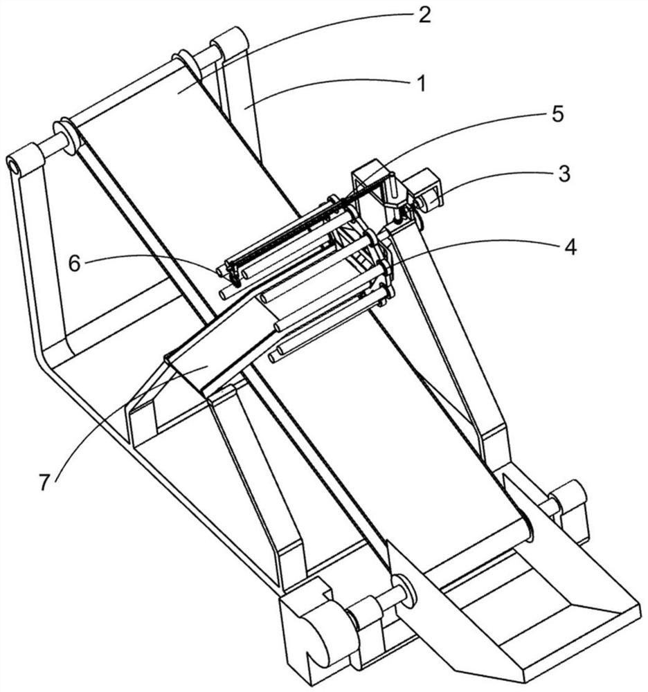
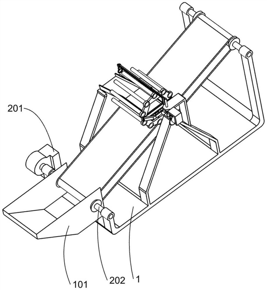
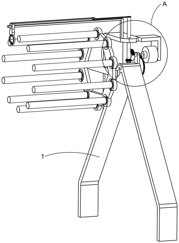
[0028] A high metal soil removal device for soil remediation, such as Figure 1-10 As shown, it includes a support 1, a funnel 101, a transmission mechanism 2, a drive mechanism 3, a metal adsorption mechanism 4, a repeating transmission mechanism 5 and an automatic retraction mechanism 6 for scraping. The funnel 101 for placing soil is fixed on the support One end of the seat 1, the transmission mechanism 2 for transmitting the soil in the funnel 101 is arranged on the upper side of the support 1, the driving mechanism 3 is arranged on the support 1, and the transmission mechanism 2 for transferring the soil containing metal The metal adsorption mechanism 4 from which the component soil is removed is set on the drive mechanism 3 , the repeat transmission mechanism 5 is set on the support 1 and the drive mechanism 3 , and the scraping automatic contraction mechanism 6 is set on the repeat transmission mechanism 5 .
[0029] Specifically, the transmission mechanism 2 includes a...
Embodiment 2
[0035] On the basis of Example 1, such as figure 1 with Figure 7 As shown, the repeated transmission mechanism 5 is located on the support 1 and the mounting frame 301, and the repeated transmission mechanism 5 includes a power shaft 501, a bevel gear 1 502, a rotating shaft 503, a bevel gear 2 504, a rotating rod 505, and a connecting rod 505. Rod 506, sliding rod 1 507 and sliding sleeve 508, described power shaft 501 is arranged on the bearing 1 and is fixedly connected with the output shaft of driving motor 303, and described bevel gear 1 502 is fixedly arranged on one end of power shaft 501 And the first bevel gear 502 is a tooth-less bevel gear, the rotating shaft 503 is arranged on the mounting frame 301 through a bearing and is located above the support 1, and the second bevel gear 504 is fixedly arranged at the lower end of the rotating shaft 503 and is connected with the bevel gear One 502 is engaged, the rotating rod 505 is fixedly arranged on the upper end of the...
Embodiment 3
[0039] On the basis of Example 2, such as figure 1 , Figure 9-10 As shown, it also includes a metal discharge mechanism 7 for collecting scraped metal soil. The metal discharge mechanism 7 is arranged on the support 1. The metal discharge mechanism 7 includes a fixed rod 701, a movable sleeve 702, a collection Plate 703, mounting block 704 and roller 705, the fixed rod 701 is fixed on the end of the support 1 away from the mounting frame 301, the movable sleeve 702 is movably arranged on the fixed rod 701, and the The collecting plate 703 that collects metal soil is fixed on the movable sleeve 702, the mounting block 704 is fixed on one side of the collecting plate 703 and is close to the rotating frame 401, and the roller 705 is rotatably mounted on the mounting block 704 and the roller 705 is in contact with the inner ring of the rotating frame 401, and the rotating frame 401 and the roller 705 cooperate to drive the collecting plate 703 to swing up and down.
[0040] Aft...
PUM
 Abstract
Description
Claims
Application Information
 - R&D
- Intellectual Property
- Life Sciences
- Materials
- Tech Scout
- Unparalleled Data Quality
- Higher Quality Content
- 60% Fewer Hallucinations
Browse by: Latest US Patents, China's latest patents, Technical Efficacy Thesaurus, Application Domain, Technology Topic, Popular Technical Reports.
© 2025 PatSnap. All rights reserved.Legal|Privacy policy|Modern Slavery Act Transparency Statement|Sitemap|About US| Contact US: help@patsnap.com


