
Planing machine positioning clamp for Roots blower impellers

A Roots blower and positioning fixture technology, applied in positioning devices, planers/slotting machines, clamping and other directions, can solve the problems of reducing the subsequent use of the device, impeller support, impeller deformation, etc., and achieve the effect of facilitating subsequent use and avoiding shaking

Pending Publication Date: 2020-11-17
山东三牛机械集团股份有限公司
View PDF0 Cites 0 Cited by
  • Summary
  • Abstract
  • Description
  • Claims
  • Application Information

AI Technical Summary

Problems solved by technology

[0004] The purpose of the present invention is to provide a positioning fixture for a Roots blower impeller planer, which solves the problem that the existing planer positioning fixtures on the market cannot automatically support the impeller when clamping the Roots blower impeller, and need to manually support it. It will cause inconvenience to support the impeller and reduce the subsequent use of the device, and most of the positioning fixtures are connected by a planer. If the positioning fixture is used for a long time, it will inevitably be worn and damaged, and it is inconvenient for the staff to disassemble the positioning fixture. Control and adjust the strength to avoid the deformation of the impeller

Method used


Image

  • Planing machine positioning clamp for Roots blower impellers
  • Planing machine positioning clamp for Roots blower impellers
  • Planing machine positioning clamp for Roots blower impellers

Examples


Embodiment Construction

[0026] The following will clearly and completely describe the technical solutions in the embodiments of the present invention with reference to the accompanying drawings in the embodiments of the present invention. Obviously, the described embodiments are only some, not all, embodiments of the present invention. Based on the embodiments of the present invention, all other embodiments obtained by persons of ordinary skill in the art without making creative efforts belong to the protection scope of the present invention.

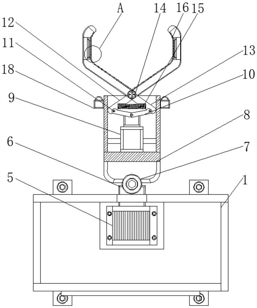
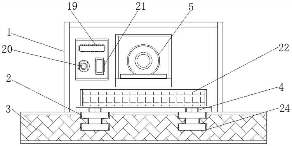
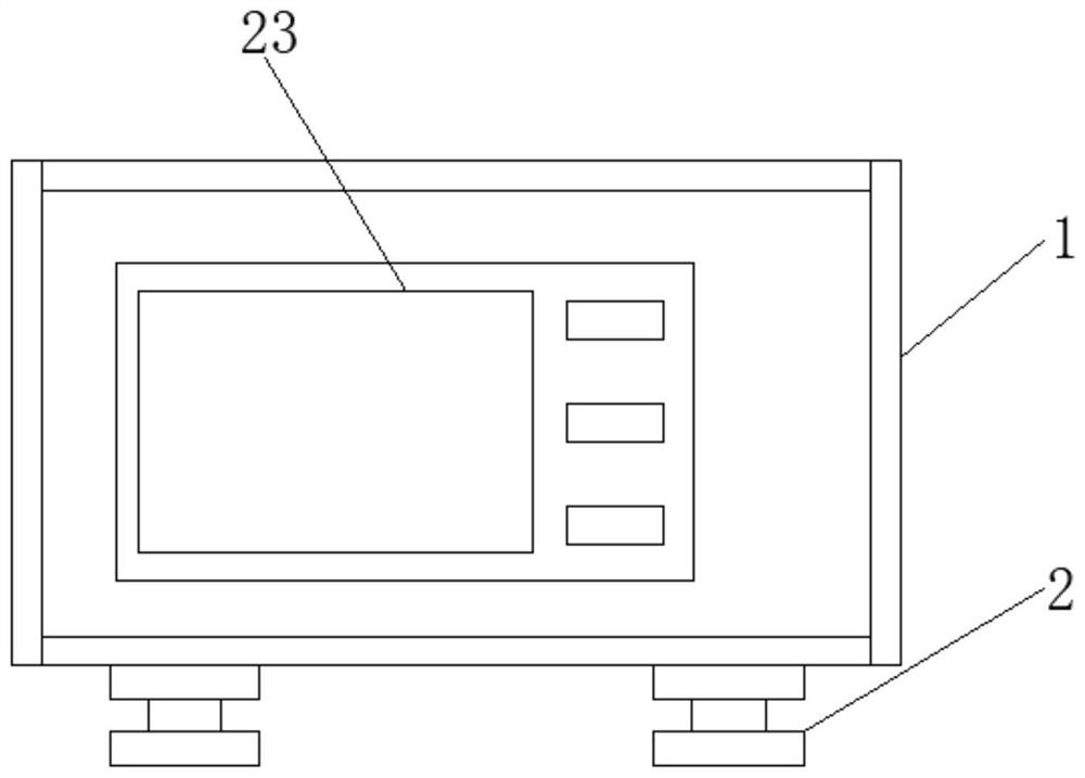
[0027] see Figure 1-5 , a positioning fixture for a Roots fan impeller planer, including a main body 1, a positioning slider 2, a workbench 3, a positioning bolt 4, a servo motor 5, a limit rod 6, an electric rotating shaft 7, a positioning chamber 8, and an electric push rod 9 , connecting rod 10, positioning shaft 11, fixed rod one 12, fixed rod two 13, adjusting shaft 14, spring 15, anti-skid pattern 16, pressure detector 17, infrared detector 18, A / D conv...


PUM


Abstract

The invention discloses a planing machine positioning clamp for Roots blower impellers. The planing machine positioning clamp for the Roots blower impellers comprises a main body and an electric pushrod; a positioning sliding block is arranged at the lower end of the main body, a workbench is arranged on the outer side of the positioning sliding block, a positioning bolt is arranged inside the positioning sliding block, a servo motor is arranged inside the main body, a limiting rod is arranged at the output end of the servo motor, an electric rotating shaft is arranged on the outer side of the limiting rod, a positioning bin is arranged on the outer side of the electric rotating shaft, the electric push rod is arranged inside the positioning bin, and a connecting rod is arranged at the output end of the electric push rod. Through mutual cooperation of the arranged servo motor and the limiting rod, the rotating angle of the electric rotating shaft can be flexibly adjusted, so that theangles of the impellers can be adjusted according to the requirements, and the arranged electric rotating shaft can further enable the positioning bin to be adjusted at multiple angles; and subsequentuse of the device is prevented from being influenced by inconvenient angle adjustment of a worker during use.

Description

technical field [0001] The invention relates to the technical field of Roots blower impeller processing devices, in particular to a positioning fixture for a Roots blower impeller planer. Background technique [0002] The Roots blower is a volumetric fan, with the end face of the impeller and the front and rear end covers of the fan. The principle is a rotary compressor that uses two leaf-shaped rotors to move relative to each other in the cylinder to compress and deliver gas. This type of blower has a simple structure and is easy to manufacture. It is widely used in aquaculture aeration, sewage treatment aeration, and cement transportation. It is more suitable for gas transportation and pressurization systems in low-pressure situations, and can also be used as a vacuum pump. It is a kind of positive displacement fan. There are two three-leaf impellers that rotate relatively in the space sealed by the casing and wall panels. Since each impeller adopts the envelope of an inv...

Claims


Application Information

Patent Timeline
Patent Type & Authority Applications(China)
IPC IPC(8): B23D7/00B23Q3/06G01L9/00
CPCB23D7/00B23Q3/062G01L9/00
Inventor 牛余会翟荣芝李冠军袁潇庭
Owner 山东三牛机械集团股份有限公司
Learn More