Machine tool machine frame for precision instrument machining

A technology of precision instruments and machine tools, used in metal processing machinery parts, metal processing equipment, manufacturing tools, etc., can solve the problems of poor shock absorption and machine tool wear, etc., to achieve the effect of easy operation and avoid vibration and wear

Inactive Publication Date: 2020-11-17
李经缙
View PDF13 Cites 1 Cited by
  • Summary
  • Abstract
  • Description
  • Claims
  • Application Information

AI Technical Summary

Problems solved by technology

[0003] The object of the present invention is to provide a machine tool frame for precision instrument processing, to solve the existing machine tool frame for precision instrument processing proposed in the above-mentioned background technology, because the shock absorption effect between the machine tool and the frame is poor, so that when moving , will cause serious wear and tear of machine tool equipment

Method used


Image

  • Machine tool machine frame for precision instrument machining
  • Machine tool machine frame for precision instrument machining
  • Machine tool machine frame for precision instrument machining

Examples


Embodiment 1

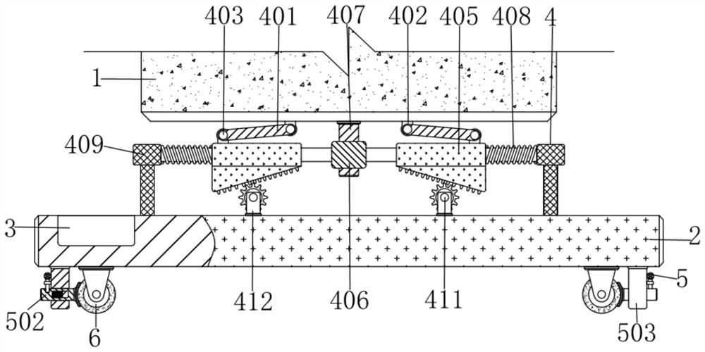
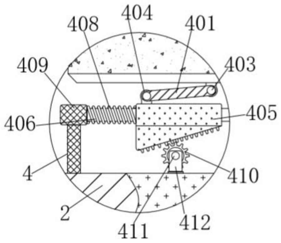
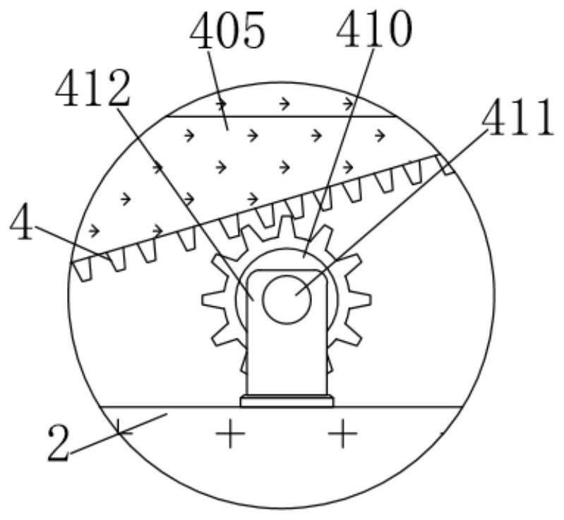
[0032]A machine tool frame for precision instrument processing, comprising a machine tool 1, a frame 2 is installed under the machine tool 1, a buffer mechanism 4 is installed between the machine tool 1 and the frame 2, and the buffer mechanism 4 includes a diagonal bar 401, a first support seat 402, the first pin shaft 403, the second support seat 404, the swash plate 405, the first cross bar 406, the first vertical bar 407, the compression spring 408, the support rod 409, the gear 410, the second pin shaft 411 and the support plate 412 , the right rear end of the left diagonal bar 401 is provided with a first support seat 402, the top of the first support seat 402 is affixed to the left bottom end of the machine tool 1, and the right rear end of the diagonal bar 401 passes through the first pin The shaft 403 is connected to the lower front end of the first support base 402 in rotation, and the oblique bar 401 moves on the first support base 402 through the first pin shaft 403...

Embodiment 2

[0034] As an option, see figure 1 , 5 And 6, the machine tool frame for precision instrument processing, the bottom four corners of the frame 2 are all equipped with a limit mechanism 5, the limit mechanism 5 includes a rubber pad 501, a second cross bar 502, a second vertical bar 503, a chute 504, The slider 505, the card slot 506, the third vertical bar 507 and the third cross bar 508, the outer wall of the right depression of the left front rubber pad 501 is attached to the lower left outer wall of the roller 6, and the rubber pads 501 at the four corners are attached to each other. Fit on the rollers 6 at the four corners to limit the movement of the rollers 6, so that the machine tool 1 on the frame 2 is stable on the ground, the middle of the left end of the rubber pad 501 is fixedly connected with the right end of the second crossbar 502, and the second crossbar 502 The middle outer wall of the second vertical bar 503 is matched with the lower inner wall of the gap, th...

Embodiment 3

[0037] The application of the machine tool frame for precision instrument processing, when using the machine tool frame for precision instrument processing, firstly, the frame 2 can move the position of the machine tool 1 on the frame 2 through the rollers 6 at the four corners, and the machine tool 1 passes through the position during transportation. The inclined bars 401 on both sides drive the inclined plates 405 on both sides to move outward on the outer walls of both sides of the first cross bar 406 to compress the compression springs 408 on both sides, otherwise the elasticity of the compression springs 408 on both sides can offset the impact of the machine tool 1 The external force exerts a buffering effect on the machine tool 1 to avoid vibration and wear of the equipment on the machine tool 1. The chute 504 in the second crossbar 502 at the four corners is on the slider 505 in the through groove on the second vertical bar 503 to the inside Sliding can make the rubber p...


PUM


Abstract

The invention discloses a machine tool machine frame for precision instrument machining. The machine tool machine frame comprises a machine tool, wherein a machine frame body is installed below the machine tool, a buffer mechanism is installed between the machine tool and the machine frame body, and a first supporting base is arranged at the rear end of the right side of an inclined rod on the left side. According to the machine tool machine frame for precision instrument machining, external force borne by the machine tool can be offset through elasticity of compression springs on the two sides, the buffering effect on the machine tool is achieved, vibration abrasion of equipment on the machine tool is avoided, and the problem that for an existing machine tool machine frame for precision instrument machining, due to the poor damping effect between the machine tool and a machine frame, when moving, machine tool equipment is seriously abraded; and the machine tool on the machine frame can be moved through rolling wheels at the four corners of the machine frame, so that the machine tool is convenient to transport, the working difficulty of workers is reduced, and the problems that theexisting machine tool machine frame for precise instrument machining is inconvenient to carry, and the working difficulty is provided for the workers are solved.

Description

technical field [0001] The invention relates to the technical field of precision instruments, in particular to a machine tool frame for processing precision instruments. Background technique [0002] Precision instruments refer to equipment and devices used to generate and measure precision quantities, including observation, monitoring, measurement, verification, recording, transmission, transformation, display, analysis, processing and control of precision quantities. Precision instruments are an important part of instrumentation branch, which needs machine tools to process, but the existing machine tool frame for precision instrument processing, due to the poor shock absorption effect between the machine tool and the frame, when moving, it will cause serious wear and tear on the machine tool equipment, and there are existing The machine tool frame for precision instrument processing is not easy to carry, which provides workers with the problem of difficulty in work. Cont...

Claims


Application Information

Patent Timeline
Patent Type & Authority Applications(China)
IPC IPC(8): B23Q1/00B23Q1/01B23Q11/00
CPCB23Q1/00B23Q1/01B23Q11/0032
Inventor 李经缙
Owner 李经缙
Why Eureka
Try Eureka