Nondestructive vertical automatic wire drawing method for optical fibers

An optical fiber, non-damaging technology, applied in glass fiber drawing devices, glass manufacturing equipment, manufacturing tools, etc., can solve problems such as uneven diameter of twisted wire drawing, scalding rubber drawing wheel, slipping of optical fiber wire, etc., to achieve wire drawing Process stabilization, reduced surface contact and skin wear, improved surface quality and better results

Active Publication Date: 2020-11-17
CHINA BUILDING MATERIALS ACAD
View PDF3 Cites 0 Cited by
  • Summary
  • Abstract
  • Description
  • Claims
  • Application Information

AI Technical Summary

Problems solved by technology

Wheel pulling mainly relies on the rotational friction of the rubber drawing wheel to achieve the drawing of the optical fiber filament. During the drawing process, the optical fiber and the rubber surface of the drawing wheel are in full contact with the friction force to produce a pull-down effect. Due to friction The contact process causes the surface of the optical fiber to be easily damaged. When the drawing temperature is high, it is easy to burn the surface of the rubber drawing wheel, which will cause impurities or foreign matter pollution on the surface of the optical fiber and reduce the surface quality of the optical fiber. ; When the drawing temperature is low, the optical fiber is very easy to slip with the rubber drawing wheel and cannot be drawn normally, or the surface of the optical fiber will be cortical and glass-abrasive.
The way of pulling is mainly to rely on the rubber pad on the timing belt to clamp and draw the optical fiber, which is also very prone to slippage of the optical fiber or twisting or drawing of the optical fiber during the drawing process. Due to problems such as uneven diameter, it is often necessary to manually intervene in the entire drawing process, which makes the surface of the optical fiber very prone to damage, adhesion of colloidal particles, impurities, or deterioration of the perpendicularity and concentricity of the drawn optical fiber. As a result, the drawing quality of the optical fiber yarn is reduced, and spots appear inside the prepared optical fiber image transmission element, which easily makes the entire product scrapped

Method used


Image

  • Nondestructive vertical automatic wire drawing method for optical fibers
  • Nondestructive vertical automatic wire drawing method for optical fibers
  • Nondestructive vertical automatic wire drawing method for optical fibers

Examples


Embodiment 1

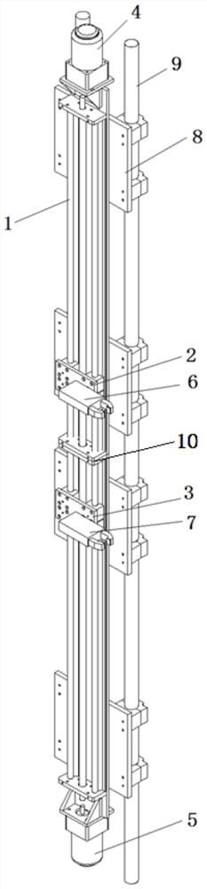
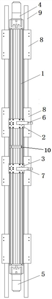
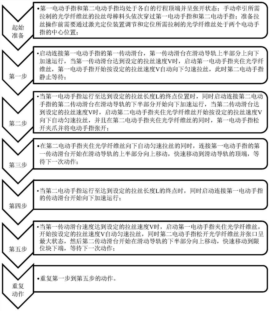
[0063] see image 3 , a method for non-damaging vertical automatic drawing of optical fibers, comprising the following steps:

[0064] Initial preparation: Both the first electric finger and the second electric finger are at the top of their respective strokes and their openings are at the maximum state; the drawing head of the optical fiber to be drawn is manually pulled through the first electric finger and the second electric finger in turn. Fingers: before the wire drawing operation, the laser positioning device needs to be used to adjust and position the optical fiber wire to be drawn in the center of the two electric fingers;

[0065] The first electric finger is at the top of the stroke of the upper half of the sliding guide rail, and the second electric finger is at the top of the stroke of the lower half of the sliding guide rail. The sliding guide rail is divided into the upper half and the lower half by the limit block; the length of the sliding guide rail is 1600mm...

Embodiment 2

[0075] The steps are the same as in Example 1, except that the drawing speed V is 70 mm per second, the drawing distance L is 800 mm, and the length of the sliding guide rail is 2000 mm.

Embodiment 3

[0077] The steps are the same as in Example 1, except that the wire drawing speed V is 20 mm per second, the wire drawing distance L is 400 mm, and the length of the sliding guide rail is 1200 mm.

[0078] The invention sets, adjusts and controls the wire drawing speed of the transmission slide, the return speed of the transmission slide, and the wire drawing length of the transmission slide through an intelligent control system; an optical fiber non-damage automatic wire drawing system of the present invention is used for automatic wire drawing, The splint of the electric finger is used to clamp the optical fiber. The splint of the electric finger is in contact with the optical fiber through point contact, forming a point-contact drawing traction method. The transmission slide and the electric finger are not in contact with the optical fiber during the traction process. The contact or touch of other positions of the filament reduces the contact with the optical fiber filament,...


PUM

PropertyMeasurementUnit
Lengthaaaaaaaaaa
Ellipticityaaaaaaaaaa
Diameteraaaaaaaaaa

Abstract

The invention discloses a nondestructive vertical automatic wire drawing method for optical fibers. The method comprises the steps that a first electric finger and a second electric finger are respectively positioned at the top ends of respective strokes at the beginning, a first transmission sliding table accelerates downwards and starts the first electric finger to clamp an optical fiber wire atthe beginning of wire drawing, the first electric finger loosens a clamping jaw when the first transmission sliding table moves to an end point, a second transmission sliding table begins to accelerate downwards and starts the second electric finger to clamp the optical fiber wire for downward wire drawing at the same time, and the first transmission sliding table quickly moves to the top end ofa sliding guide rail at the moment; and when the second electric finger moves to the end point of a wire drawing length L, the second electric finger is loosened, the first transmission sliding tableis started to begin downward accelerated operation, the first electric finger is started to perform automatic wire drawing, and then the second transmission sliding table starts to quickly move to thetop end of the stroke to wait for repeating of the next action. Through the nondestructive automatic wire drawing method, the surface contact and skin layer damage of the optical fiber are reduced, and the drawing surface quality of the optical fiber and the stability of a wire diameter are improved.

Description

technical field [0001] The invention relates to the technical field of optical fiber manufacturing and processing, in particular to a non-damaging vertical automatic drawing method for optical fibers. Background technique [0002] Optical fiber imaging components, including optical fiber panels, optical fiber inverters, optical fiber cones, optical fiber imaging bundles, and microchannel plates, are photoelectric imaging components with excellent performance, with simple structure, small size, and light weight. , high resolution, large numerical aperture, small inter-stage coupling loss, clear and true image transmission, high light transmission efficiency, optical zero thickness in image transmission, and improved edge image quality. Optical fiber image transmission components are widely used in various cathode ray tubes, camera tubes, charge-coupled device (CCD, Charge-coupled Device) couplings, medical device display screens and high-speed High-definition television imag...

Claims


Application Information

Patent Timeline
IPC IPC(8): C03B37/027
CPCC03B37/027C03B37/0253C03B2205/40
Inventor 张磊贾金升张敬樊志恒许慧超于浩洋张弦汤晓峰王爱新赵越石钰宋普光洪常华
Owner CHINA BUILDING MATERIALS ACAD
Why Eureka
Try Eureka