Production method and production device of ultrafine filament

a production method and ultrafine filament technology, applied in the direction of filament/thread forming, electric/magnetic/electromagnetic heating, fibre treatment, etc., can solve the problems of complex manufacturing method, small resin particles, and lack of molecular orientation in the filament obtained, so as to improve molecular orientation and high manufacturing cost , the effect of high precision

Active Publication Date: 2010-06-17
UNIVERSITY OF YAMANASHI
View PDF12 Cites 13 Cited by
  • Summary
  • Abstract
  • Description
  • Claims
  • Application Information

AI Technical Summary

Benefits of technology

[0035]The ES method previously used to manufacture nanofibers is complex manufacturing method that requires dissolution of a polymer in a solvent and removal of the solvent from the finished product and contributes to a high manufacturing cost. In addition, the finished product also encounters quality problems such as the presence of resin pieces referred to as lumps and balls, a broad filament diameter distribution and the like. In addition, the fiber obtained was short (staple fiber), and the length ranged from several millimeters to at most several tens of millimeters. However, basically continuous filaments that are at least several meters long can be obtained by using the present invention.
[0036]The present invention does not need a special high performance apparatus that operates at high precision, and a microfilament with improved molecular orientation can be obtained readily using a simple means. In addition, a draw ratio of at least 10,000 can be achieved using almost all thermoplastic polymers, and a super fine filament with a diameter of less than 1 μm in the nanofilament range can be manufactured. Furthermore, a super fine filament with a very narrow filament diameter distribution reflected in a standard deviation of 0.1 or lower can be obtained even though the average filament diameter is in the nanofilament range.
[0037]The pressure difference upstream and downstream from an orifice is utilized as the means to generate a high speed gas flow that imparts the drawing tension in the super drawing method of the present invention involving an infrared light beam. The approach creates a very stable high speed gas flow and yields not only a nanofilament but also enables a stable continuous operation as far as productivity is concerned.
[0038]The drawing process of the present invention is particularly stable due to the reduced pressure in the drawing chamber, and a stable nanofilament manufacturing process can be realized. An air flow released at high speed is not disturbed under reduced pressure, and a stable air flow is thought to be achieved.
[0039]In addition, the present invention can present long fiber non-woven fabrics comprising super fine filaments with diameters in the nanofilament range. Furthermore, a laminated material is also obtained by laminating the filament on non-woven fabrics such as commercially available spun bonded non-woven fabrics and the like.
[0040]The present invention can yield a super fine filament with a diameter in the nanofilament range from a filament comprising biodegradable polymers used in regenerated medical materials such as poly(lactic acid) and poly(glycolic acid) and the like that ordinarily have poor drawing properties. The ES method previously used to manufacture nanofibers used a solvent such as chloroform and the like, and the method not only required dissolution step and solvent removal step but also used such toxic solvents. The use of such solvents made it difficult to use the filaments in regenerated medical treatment applications.

Problems solved by technology

However, the ES method is a complicated manufacturing method since polymer needs to be dissolved in solvent and the solvent must be removed from the product obtained.
In addition, molecules lack orientation in the filament obtained, and many quality problems such as the presence of small resin particles, referred to as balls and shots were encountered in the fiber aggregates obtained.

Method used


Image

  • Production method and production device of ultrafine filament
  • Production method and production device of ultrafine filament
  • Production method and production device of ultrafine filament

Examples


example 1

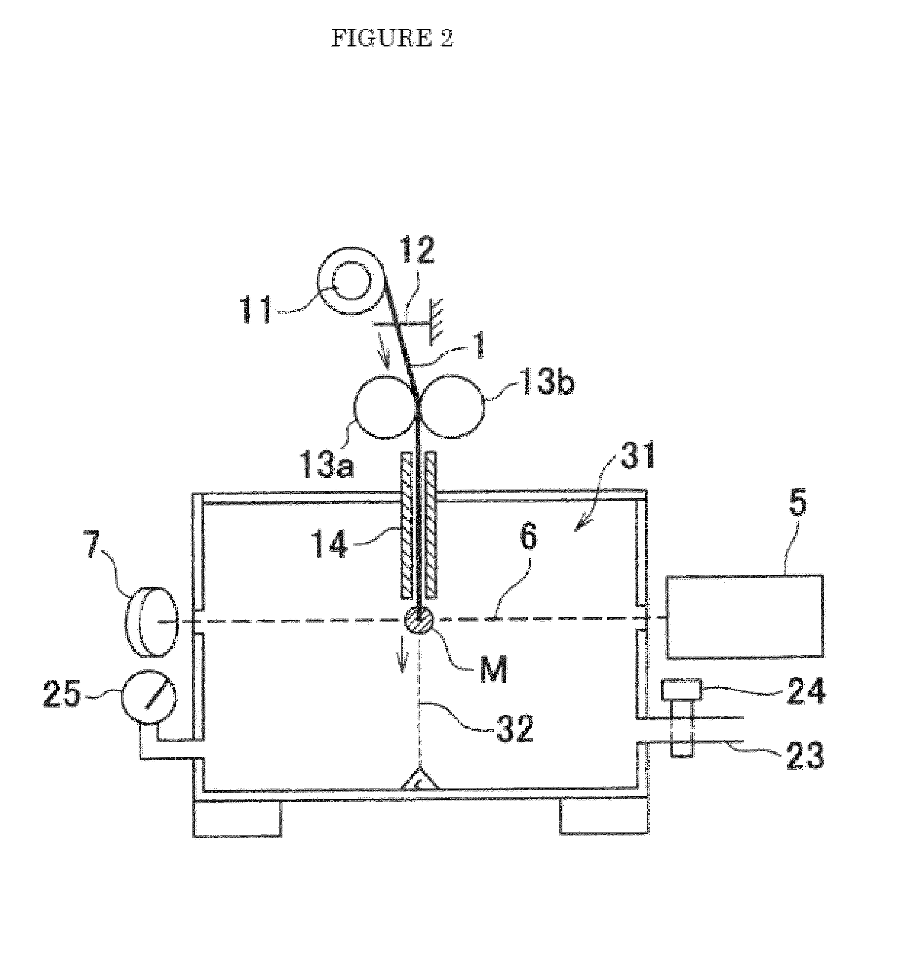
[0066]An undrawn poly(ethylene terephthalate) (PET) filament (filament diameter 182 μm) was used and was drawn using the drawing apparatus shown in FIG. 2. The laser the emitter used at this point was a carbon dioxide laser emitter with laser output of 8 W, and the beam diameter (light beam) was 2.0 mm. The type of orifice shown in FIG. 5a was used as the orifice, and the orifice diameter D2 was 0.5 mm. The degree of vacuum in the drawing chamber was adjusted to 8 KPa. The supply speed of the original filament was changed from 0.1 m / min to 0.2 m / min, 0.3 m / min and 0.4 m / min, and the filament diameters of the filaments obtained are shown in Table 2. In addition, the filament diameters when the laser output was changed from two watts to eight watts are also shown. According to the data in the table, a nanofiber with an average filament diameter of 0.313 μm (313 nanometers) was obtained when using eight watts of laser power and a supply speed of 0.1 m / min. The standard deviation for th...

example 2

[0067]The same undrawn poly(ethylene terephthalate) filament used in Example 1 was used as the original filament. The same drawing chamber and laser emitter used in Example 1 were used. The experiment was conducted using a filament supply speed of 0.1 m / min at different degrees of vacuum for the drawing chamber. When the degree of vacuum was 8 KPa, the average filament diameter was 0.31 μm as shown in Example 1. When the degree of vacuum was 6 KPa, the average filament diameter was 0.42 μm. When the degree of vacuum was 24 KPa, The average filament diameter was 0.82 μm. Filaments with filament diameters less than 1 μm were obtained even under these conditions.

example 3

[0068]An undrawn poly(lactic acid) (PLLA) filament (filament diameter 75 μm) was used as the original filament and was drawn using the drawing apparatus of FIG. 2. A carbon dioxide gas laser emitter with a laser output of eight watts was used for this case, and the beam diameter (light beam) was 2.0 mm. The type of orifice described in FIG. 5(a) was used as the orifice, and the orifice diameter d2 was 0.5 mm. The degree of vacuum in the drawing chamber was adjusted to 8 kPa. The original filament supply speed was changed from 0.1 m / min to 0.8 m / min, and the filament diameters of the filaments obtained are shown in Table 4. In addition, the filament diameters when the laser output was changed from two watts to eight watts are also shown in the table. According to the data in the table, a nanofiber with an average filament diameter of 0.13 μm (130 nanometer) was obtained when the laser power was eight watts (watt density 256.6 W / cm2) and the supply speed was 0.1 m / min. The filament di...


PUM

PropertyMeasurementUnit
diameteraaaaaaaaaa
pressureaaaaaaaaaa
air speedaaaaaaaaaa

Abstract

The objective of the present invention is to enable a microfilament that is a nanofilament to be manufactured continuously and consistently from all thermoplastic polymers without requiring a specialized high precision.high performance apparatus and also to present the nanofilament manufactured as described. The present invention comprises a microfilament in a nanofilament region and the manufacturing means thereof wherein a original filament transferred using a filament transfer means is supplied to an orifice under pressure P1 and is heated and drawn using an infrared light beam directly under the orifice under pressure P2 (P1>P2).

Description

FIELD OF THE INVENTION[0001]The present invention relates to microfilament manufacturing method and manufacturing apparatus therefore and the nanofilament obtained. More specifically, the present inventions relate to microfilament manufacturing means that enables the microfilament to be attenuated until it is nanofilament by achieving a super high draw ratio by irradiating using an infrared light beam.BACKGROUND OF THE INVENTION[0002]Fibers with fiber diameters smaller than 1 μm, that is, nanometer sized (from several nanometers to several hundreds of nanometers) fibers have gained attention in recent years as revolutionary materials of the future in a broad range of applications such as IT, bio, environmental and other applications. The nanofibers have typically been prepared using an electro-spinning method (henceforth sometimes abbreviated to “ES method”). (See U.S. Pat. No. 1,975,504; You Y., et al Journal of Applied Polymer Science, Vol. 95, p. 193-200, 2005.) However, the ES m...

Claims


Application Information

Patent Timeline
Patent Type & Authority Applications(United States)
IPC IPC(8): B29C55/00D04H3/00
CPCD04H3/00D02J1/22
Inventor SUZUKI, AKIHIRO
Owner UNIVERSITY OF YAMANASHI
Why Eureka
Try Eureka