
Driving backplane, light-emitting panel, display device, and molding method

A technology for driving backplanes and light-emitting panels, which is applied in the fields of display devices, light-emitting panels, and driving backplanes. It can solve problems such as high current and damage to light-emitting module components, and achieve the effects of ensuring safety, wide application range, and meeting driving requirements.

Active Publication Date: 2021-11-02
SHANGHAI TIANMA MICRO ELECTRONICS CO LTD
View PDF0 Cites 0 Cited by
  • Summary
  • Abstract
  • Description
  • Claims
  • Application Information

AI Technical Summary

Problems solved by technology

Due to structural design flaws in the existing drive backplane, when a short-circuit fault occurs in the path where the light-emitting module is located, a large current will be caused, causing damage to the light-emitting module and the components in the path where it is located

Method used


Image

  • Driving backplane, light-emitting panel, display device, and molding method
  • Driving backplane, light-emitting panel, display device, and molding method
  • Driving backplane, light-emitting panel, display device, and molding method

Examples


Embodiment Construction

[0047] Features and exemplary embodiments of various aspects of the invention will be described in detail below. In the following detailed description, numerous specific details are set forth in order to provide a thorough understanding of the present invention. It will be apparent, however, to one skilled in the art that the present invention may be practiced without some of these specific details. The following description of the embodiments is only to provide a better understanding of the present invention by showing examples of the present invention. In the drawings and the following description, at least some well-known structures and techniques have not been shown in order to avoid unnecessarily obscuring the present invention; and, for clarity, the dimensions of some structures may have been exaggerated. Furthermore, the features, structures, or characteristics described hereinafter may be combined in any suitable manner in one or more embodiments.

[0048]The orienta...


PUM


Abstract

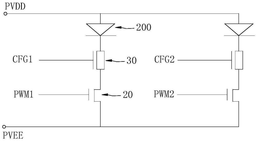
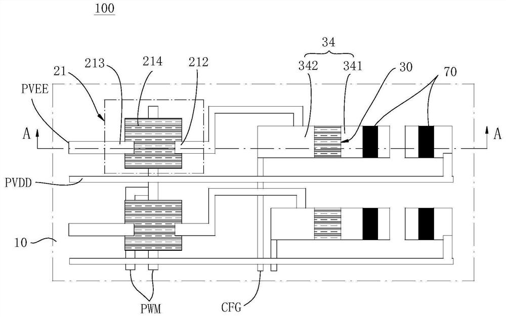
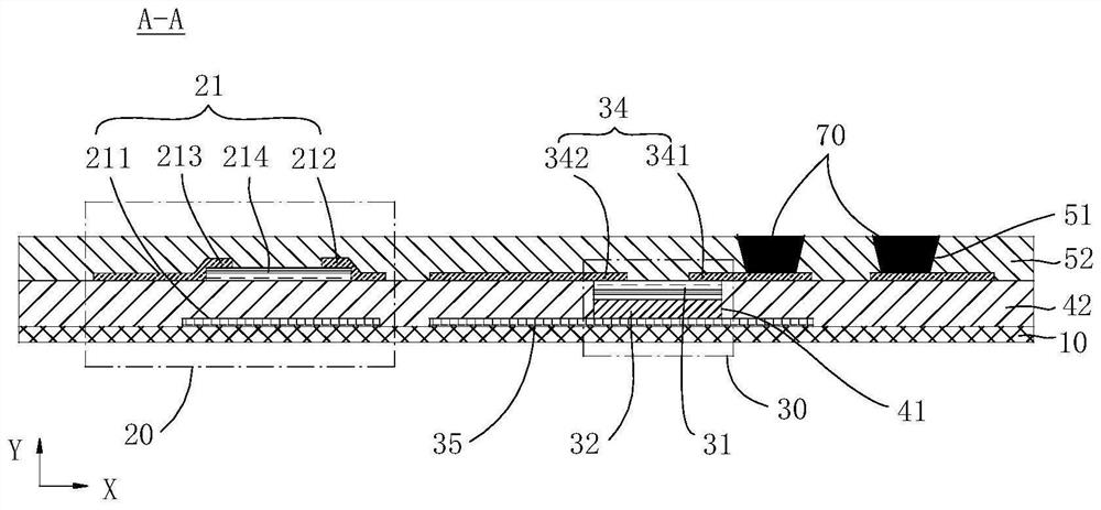
The invention relates to a driving backplane, a light-emitting panel, a display device and a molding method. The driving backplane includes: a base; a driving unit, a plurality of driving units are distributed in an array of the base, and each driving unit is used to drive a light-emitting module; the driving unit includes The driving module and the overcurrent protection module, the overcurrent protection module includes a first semiconductor layer and a second semiconductor layer with opposite polarities and a depletion layer can be formed between each other, and the light emitting module can be connected in series with the driving module and the first semiconductor layer A path is formed between the first power supply terminal and the second power supply terminal, and the width of the depletion layer between the first semiconductor layer and the second semiconductor layer can be adjusted to adjust the impedance of the access path part of the first semiconductor layer. The invention can adjust the current of the path where the light-emitting module is located, and avoid damage to components in the path where the light-emitting module is located.

Description

technical field [0001] The invention relates to the field of display technology, in particular to a driving backplane, a light-emitting panel, a display device and a molding method. Background technique [0002] Light emitting modules such as LED (Light Emitting Diode, light emitting diode), mini LED (mini light emitting diode), micro LED (micro light emitting diode) are widely used in lighting and display technology fields. [0003] In order to better drive the light emitting module to emit light to realize lighting or display, it is necessary to set a driving backplane for controlling the light emitting module. Due to defects in structural design of the existing drive backplane, when a short-circuit fault occurs in the path where the light-emitting module is located, a large current will be caused, causing damage to the light-emitting module and components in the path where it is located. Contents of the invention [0004] Embodiments of the present invention provide a ...

Claims


Application Information

Patent Timeline
Patent Type & Authority Patents(China)
IPC IPC(8): G09G3/32H01L27/15
CPCG09G3/32G09G2300/0876G09G2310/0264G09G2310/0278H01L27/156
Inventor 马从华孙晓平东强王丽花
Owner SHANGHAI TIANMA MICRO ELECTRONICS CO LTD
Learn More