
Externally-hung automatic adjustment solar device

A solar device and automatic adjustment technology, applied in mobile/directional solar collectors, solar thermal energy, solar thermal power generation, etc., can solve the problems of solar panels that cannot be automatically deployed and stored, corrosion, and panel damage

Pending Publication Date: 2020-11-17
周友金
View PDF0 Cites 1 Cited by
  • Summary
  • Abstract
  • Description
  • Claims
  • Application Information

AI Technical Summary

Benefits of technology

This invention relates to an apparatus for adjustably tilting or positioning a light-focal plane (LF) with one axis perpendicularly aligned towards the sky when it receives more strong sunshine than usual. It uses memristive materials called springs instead of metals like copper because they can change their shape under different conditions such as heat or pressure without losing effectiveness over time. By doing these changes, LF panels are able to pivot upward slightly from horizontal angles during times where there may be less direct exposure to bright sunrays compared to traditional methods.

Problems solved by technology

The technical problem addressed by this patented technology relates to prevention from damaging or disruptive impacts caused when sunlight hits certain surfaces that may cause water droplets onto them due to changing environmental conditions such as wind speed or temperature.

Method used


Image

  • Externally-hung automatic adjustment solar device
  • Externally-hung automatic adjustment solar device
  • Externally-hung automatic adjustment solar device

Examples


Embodiment Construction

[0019] The following will clearly and completely describe the technical solutions in the embodiments of the present invention with reference to the accompanying drawings in the embodiments of the present invention. Obviously, the described embodiments are only some, not all, embodiments of the present invention.

[0020] In describing the present invention, it should be understood that the terms "upper", "lower", "front", "rear", "left", "right", "top", "bottom", "inner", " The orientation or positional relationship indicated by "outside", etc. is based on the orientation or positional relationship shown in the drawings, and is only for the convenience of describing the present invention and simplifying the description, rather than indicating or implying that the referred device or element must have a specific orientation, so as to Specific orientation configurations and operations, therefore, are not to be construed as limitations on the invention.

[0021] refer to Figure ...


PUM


Abstract

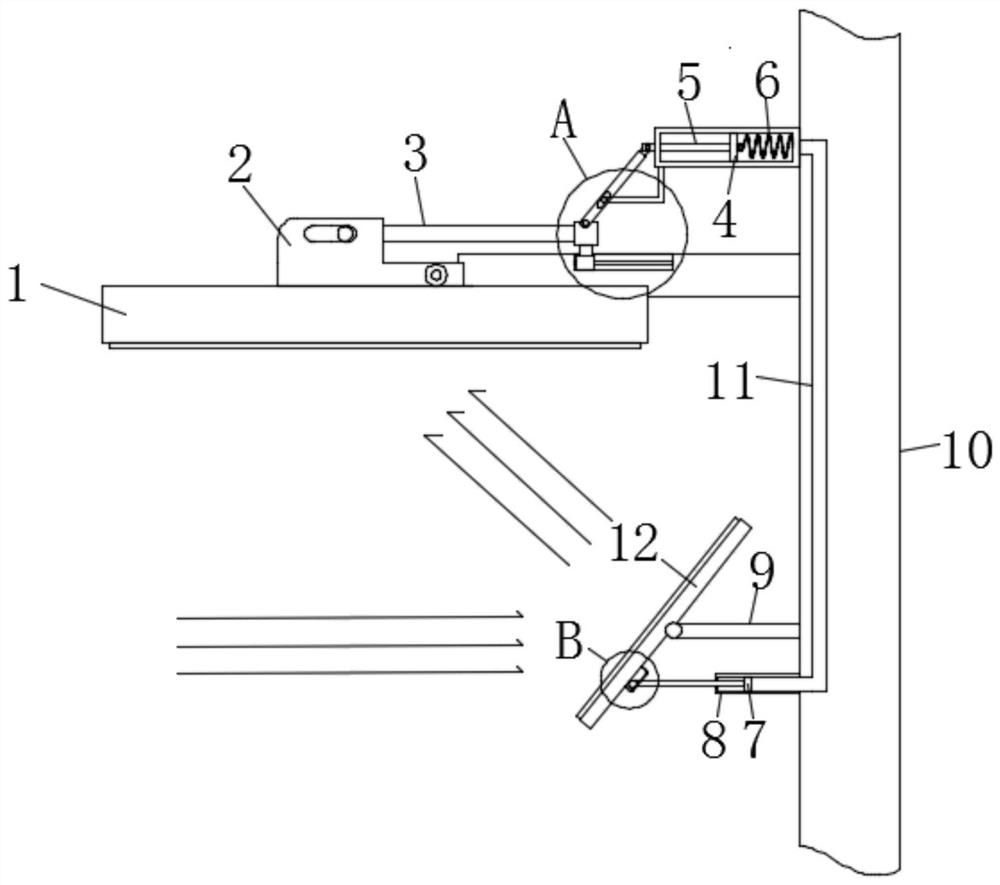
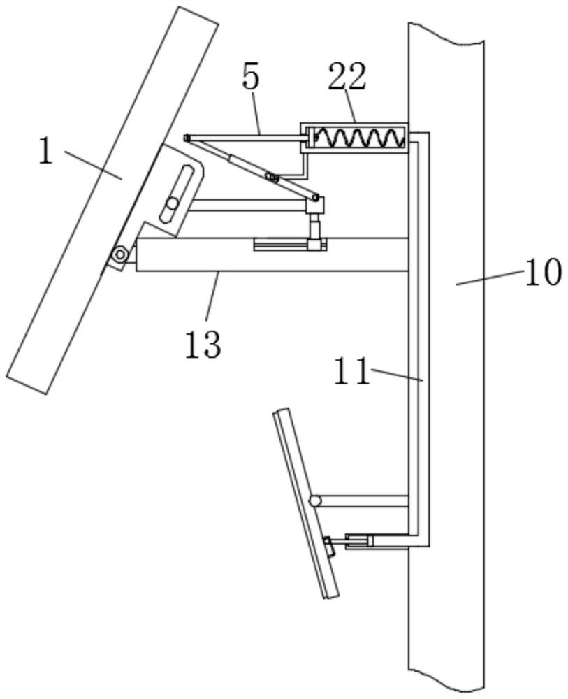
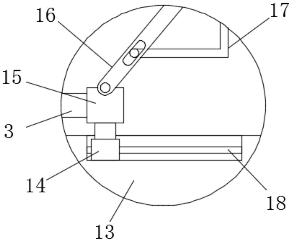
The invention discloses an externally-hung automatic adjustment solar device which comprises a mounting plate and a transverse plate, the mounting plate is fixedly mounted in a wall body, the transverse plate is fixedly mounted on the side wall of the mounting plate, a first fixing pipe is fixedly mounted on the side wall of the mounting plate, and a first sealing plug is slidably connected into the first fixing pipe; and a first push rod is fixedly installed in the center of the left end face of the first sealing plug, the other end of the first push rod penetrates through the side wall of the first fixing pipe and is rotationally connected with a rotating rod, and an L-shaped plate is fixedly installed on the bottom end face of the left end of the first fixing pipe. According to the invention, at night and in cloudy days, the memory metal spring is cooled and contracted again, so that the solar cell panel rotates anticlockwise to restore the original shape, namely, the light absorption surface of the solar cell panel is in a horizontal downward state, corrosion caused by rainwater falling on the light absorption surface of the solar cell panel is avoided, and dust falling on thelight absorption surface of the solar cell panel is reduced.

Description


Claims


Application Information

Patent Timeline
Owner 周友金
Learn More