Illuminable optical communication equipment device

An equipment device and optical communication technology, which is applied in the direction of lighting devices, lighting devices, lighting auxiliary devices, etc., can solve the problems of reducing the use efficiency of the device, the entry of external dust, reducing the service life of the device and maintenance costs, so as to avoid disassembly and installation procedures, easy disassembly and installation, and the effect of improving the use efficiency

Inactive Publication Date: 2020-11-17
广州创利宝科技有限公司
View PDF6 Cites 0 Cited by
  • Summary
  • Abstract
  • Description
  • Claims
  • Application Information

AI Technical Summary

Problems solved by technology

[0004] Aiming at the deficiencies of the prior art, the present invention provides an illuminated optical communication device, which solves the problem that the currently used communication device does not have the function of lighting and dust prevention, and cannot perform effective lighting treatment on the device according to the usage requirements. Due to the lack of dustproof function, it is easy to cause external dust to enter the interior of the device, reducing the service life and maintenance costs of the device, thereby reducing the use efficiency of the device

Method used


Image

  • Illuminable optical communication equipment device
  • Illuminable optical communication equipment device
  • Illuminable optical communication equipment device

Examples


Embodiment

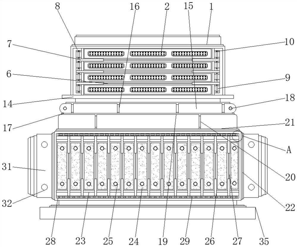
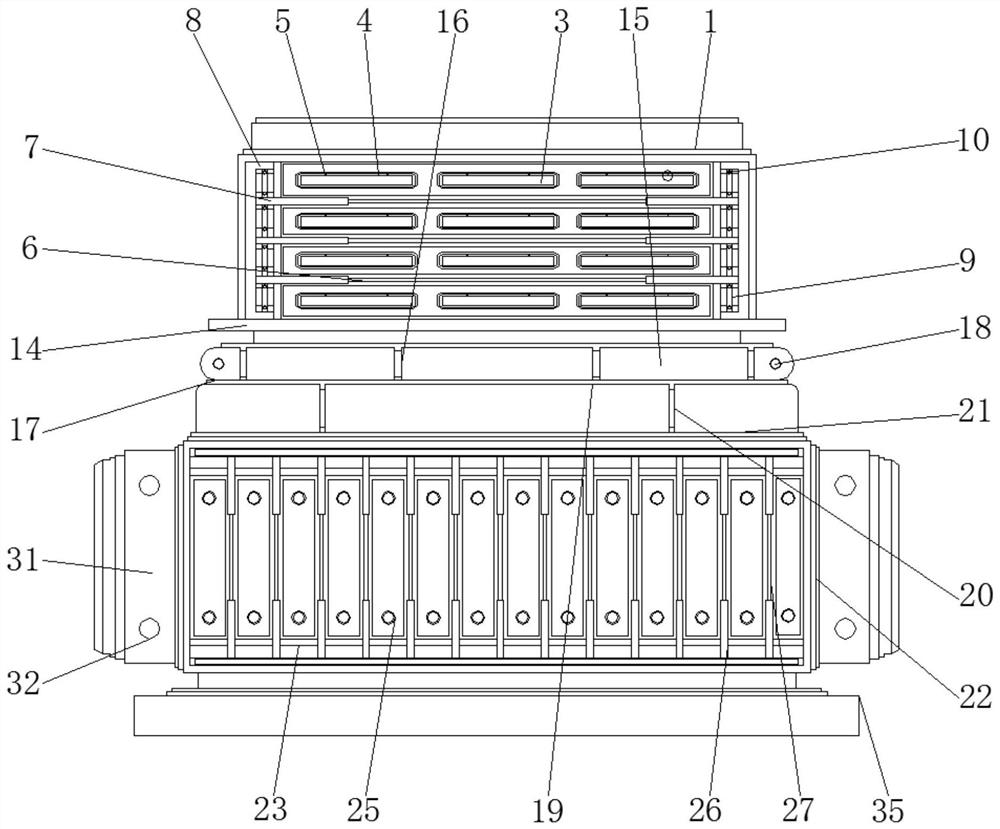
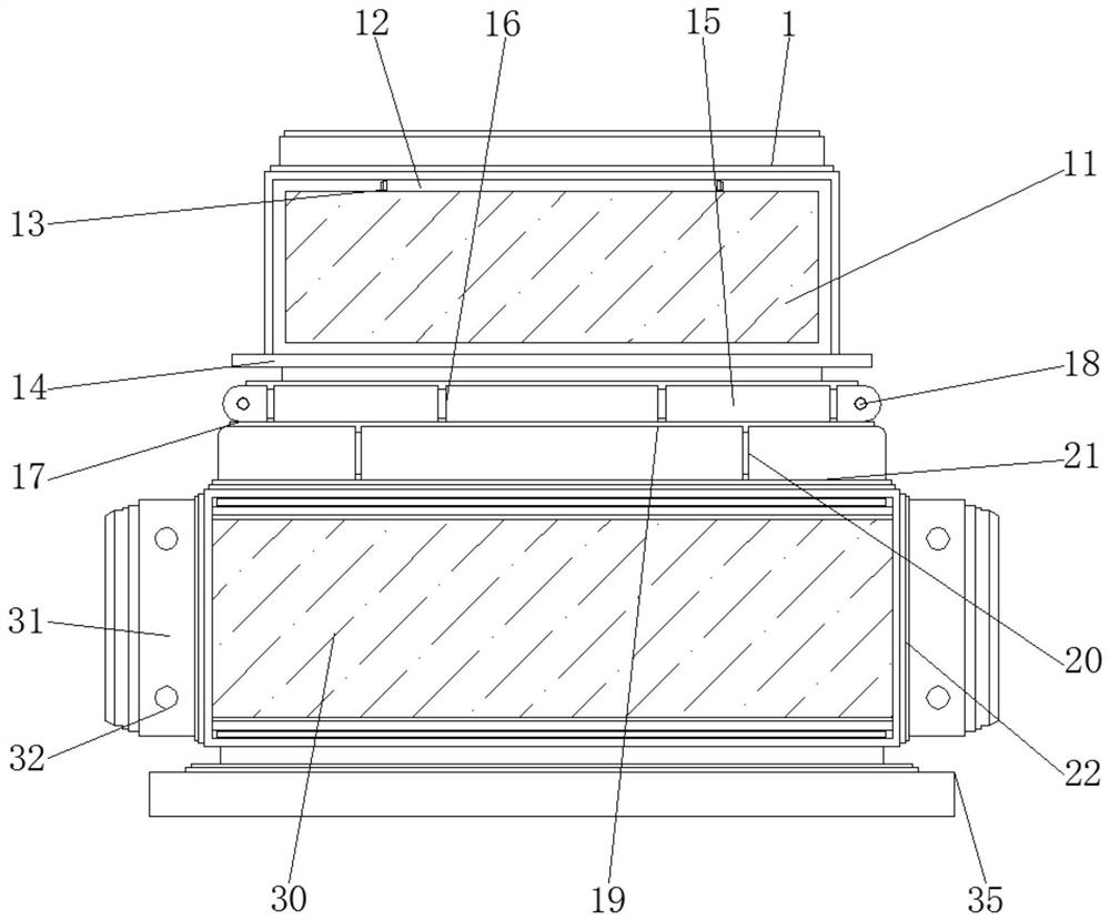
[0039] see Figure 1-6 , in this embodiment: an optical communication device that can be illuminated, including an outer frame 1, a protective cover 11, a rotating platform 14, a block 31, a vent 33 and a base 35, and the front surface of the outer frame 1 is provided with a protective cover 11 , a rotating platform 14 is arranged under the outer frame 1, and blocks 31 are arranged on both sides below the rotating platform 14, a vent 33 is arranged on the outer side and lower side of the outer frame 1, and a base 35 is arranged on the outer side and lower side of the outer frame 1, and the inner side of the outer frame 1 Both are provided with LED lamps 2, and a dustproof cover 3 is provided on the front surface of the LED lamp 2, a first rotating rod 4 is arranged above the dustproof cover 3, and first rotating bolts 5 are arranged on both sides of the first rotating rod 4, The first telescoping rod 6 is arranged below the outer side of the first rotating bolt 5, and the firs...


PUM


Abstract

The invention belongs to the related technical field of communication equipment, and particularly relates to an illuminable optical communication equipment device which comprises an outer frame, a protective cover, a rotating platform, clamping blocks, a ventilation opening and a base, the protective cover is arranged on the front surface of the outer frame, the rotating platform is arranged belowthe outer frame, and the clamping blocks are arranged on the two sides below the rotating platform. A ventilation opening is formed in the lower portion of the outer side of the outer frame, a base is arranged on the lower portion of the outer side of the ventilation opening, LED lamps are arranged in the outer frame, a dust cover is arranged on the surface of the front portion of each LED lamp,a first rotating rod is arranged above each dust cover, and first rotating bolts are arranged on the two sides of each first rotating rod. By arranging the dustproof cover, an effective protection anddustproof function can be achieved on the LED lamp, in the using process, protection and dustproof treatment can be conducted on the LED lamp according to the using requirement, the situation that the service life of the LED lamp is shortened due to the fact that external dust enters the LED lamp is avoided, and therefore the using effect of the device is effectively improved.

Description

technical field [0001] The invention relates to the related technical field of communication equipment, in particular to an optical communication equipment device capable of lighting. Background technique [0002] Optical communication equipment, communication equipment that uses light waves to transmit information, consists of signal transmission, signal transmission, and signal receiving parts. According to different transmission media, it is divided into atmospheric laser communication devices, optical fiber laser communication devices, space laser communication devices and waveguide laser communication devices. The laser communication device has the advantages of large information capacity, anti-interference, strong confidentiality, and portable equipment. However, the atmospheric laser communication device has attenuation phenomenon due to the propagation of laser light in the atmosphere, cannot cross obstacles, and is difficult to aim, which affects the communication di...

Claims


Application Information

Patent Timeline
Patent Type & Authority Applications(China)
IPC IPC(8): H04B10/116F21V33/00F21V21/00F21V15/02F21V14/02F21W131/403F21Y115/10
CPCF21V14/02F21V15/02F21V21/00F21V33/00F21W2131/403F21Y2115/10H04B10/116
Inventor 陈燕
Owner 广州创利宝科技有限公司
Why Eureka
Try Eureka