IGBT module fixing structure of PTC heater and PTC heater

A fixed structure, heater technology, applied in heating elements, ohmic resistance heating parts, electric solid devices, etc., can solve the problem of relative position deviation of IGBT modules, ensure reliability and feasibility, improve EMC effect, zero The effect of fewer parts

Pending Publication Date: 2020-11-17
SHANGHAI VMAX NEW ENERGY CO LTD
0 Cites 0 Cited by

AI-Extracted Technical Summary

Problems solved by technology

[0004] In order to solve the technical problem that the relative position of the IGBT module is easily deviated when the IGBT module is ...

Method used

Control box housing 1 is provided with the threaded hole of corresponding bead screw, and next to threaded hole is provided with locating column side by side, and bead is provided with the locating hole of corresponding locating column, aligns and locates when can facilitate bead installation, improves installation efficiency.
In another embodiment, the second locating pins only include side locating pins that can be clamped on both sides of the IGBT module, and notches are provided on both side plates of the IGBT module, and the side locating pins are clamped at the notches, It is also possible to limit the sliding of the IGBT module relative to the control box housing. Make fewer par...

Abstract

The invention discloses an IGBT module fixing structure of a PTC heater and the PTC heater, and the structure comprises a control box housing of the PTC heater, an IGBT module which is installed on the control box housing, an insulating pad which is disposed between the IGBT module and the control box housing, and a positioning plate which limits the sliding of the IGBT module relative to the control box housing through the arrangement of a positioning pin. And the pressing strip mech anism is arranged on the control box shell and is used for pressing the positioning plate. According to the invention, the bottom surface of the positioning plate is provided with the positioning pins which respectively pass through the IGBT module and the control box shell to limit the relative sliding between the IGBT module and the control box shell, and the top surface of the positioning plate is pressed by the pressing strip mechanism to limit the up-and-down movement of the positioning plate, so that the IGBT module is fixed on the control box shell. Reliability and feasibility of assembly can be guaranteed, the EMC effect is improved, the structure is simple, the number of parts is small, and cost is low.

Application Domain

Semiconductor/solid-state device detailsHeater elements +2

Technology Topic

Electrical and Electronics engineeringMechanical engineering +1

Image

  • IGBT module fixing structure of PTC heater and PTC heater

Examples

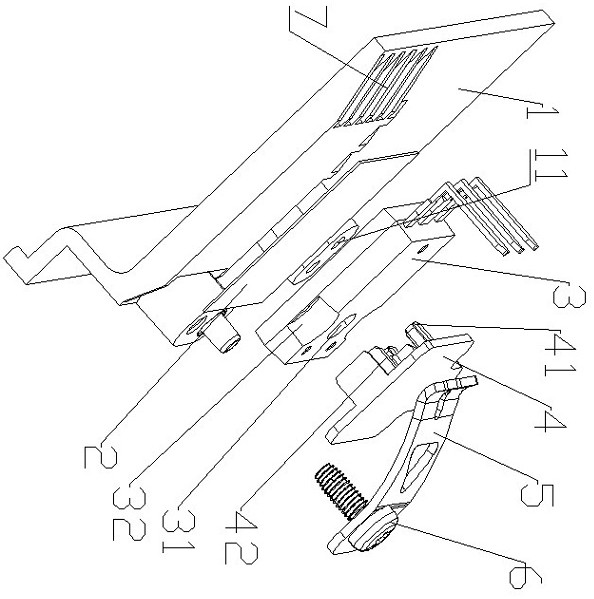
  • Experimental program(1)

Example Embodiment

[0017] In order to make the technical problems, technical solutions, and beneficial effects to be solved by the present invention clearer, the following further describes the present invention in detail with reference to the accompanying drawings and embodiments. It should be understood that the specific embodiments described here are only used to explain the present invention, but not to limit the present invention.
[0018] It should be noted that when an element is referred to as being "fixed to" or "disposed on" another element, it can be directly on the other element or indirectly on the other element. When an element is said to be "connected to" another element, it can be directly connected to the other element or indirectly connected to the other element.
[0019] In the description of the present invention, it should be understood that the terms "center", "length", "width", "thickness", "upper", "lower", "front", "rear", "left", " The orientation or positional relationship indicated by "right", "vertical", "horizontal", "top", "bottom", "inner", "outer", etc. are based on the orientation or positional relationship shown in the drawings, and are only for convenience The present invention is described and simplified description, rather than indicating or implying that the device or element referred to must have a specific orientation, be constructed and operated in a specific orientation, and therefore cannot be understood as a limitation to the present invention.
[0020] In the description of the present invention, it should be noted that the terms "installation", "connected" and "connected" should be understood in a broad sense, unless otherwise clearly specified and limited. For example, they can be fixed or detachable. Connected or integrally connected; it can be a mechanical connection or an electrical connection; it can be directly connected or indirectly connected through an intermediate medium, and it can be the internal communication of two components or the interaction relationship between two components. For those of ordinary skill in the art, the specific meanings of the above terms in the present invention can be understood according to specific circumstances.
[0021] The principle and structure of the present invention will be described in detail below with reference to the drawings and embodiments.
[0022] Such as figure 1 As shown, the present invention proposes an IGBT module fixing structure of a PTC heater, which includes: a control box housing 1, an insulating pad 2, a positioning plate 4, and a pressing mechanism of the PTC heater. The insulating pad 2 is attached to one side of the control box housing 1, the IGBT module 3 is attached to the insulating pad 2, and the bottom surface of the positioning plate 4 is provided with multiple positioning pins, which can respectively pass through the IGBT module 3 and the control box housing 1. , To limit the relative sliding between the IGBT module 3 and the control box housing 1. The beading mechanism is installed on the control box housing 1 and presses on the top surface of the positioning plate 4 to restrict the vertical movement of the positioning plate 4, so that the IGBT The module 3 is fixed on the control box housing 1. The invention can ensure the reliability and feasibility of assembly, and improve the EMC effect, and has a simple structure and few parts and low cost.
[0023] In a specific embodiment, the bottom surface of the positioning plate 4 is provided with two first positioning pins 41, the control box housing 1 is provided with a first positioning pin hole 11 corresponding to the first positioning pins 41, and the bottom surface of the positioning plate 4 is also A second positioning pin 42 is provided. The second positioning pin 42 includes side positioning pins clamped on both sides of the IGBT module and perforated positioning pins passing through the IGBT module. The IGBT module 3 is provided with a second positioning pin hole corresponding to the perforated positioning pin 31. The two side plates of the IGBT module 3 are provided with notches 32, and the side positioning pins are clamped at the notches 32. The notches 32 can be semi-circular for easy insertion.
[0024] In another embodiment, the second positioning pin only includes side positioning pins that can be clamped on both sides of the IGBT module, and there are notches on both sides of the IGBT module, and the side positioning pins are clamped at the notches, which can also restrict The sliding of the IGBT module relative to the control box housing. Makes fewer parts and lower manufacturing costs.
[0025] When the positioning plate 4 is installed, directly insert the first positioning pin 41 and the second positioning pin 42 into their corresponding positions, so that the positioning plate 4 is covered above the IGBT module 3 to limit the gap between the IGBT module 3 and the control box housing 1. Relative sliding.
[0026] The bead mechanism includes: a bead 5 and a bead screw 6. One end of the bead 5 is pressed on the positioning plate 4, and the other end is provided with a through hole. The bead screw 6 passes through the through hole of the bead 5 and is threadedly connected to the control box housing 1 so that The bead 5 is pressed against the positioning plate 4 by tightening the bead screw 6.
[0027] The control box housing 1 is provided with threaded holes corresponding to the beading screws, and positioning posts are arranged side by side of the threaded holes. The beading is provided with positioning holes corresponding to the positioning posts, which facilitates alignment and positioning during the installation of the beading, and improves installation efficiency.
[0028] In the present invention, the insulating pad 2 is specifically an insulating and heat-conducting film, which is affixed to the control box housing for easy installation. It can also be made of other insulating and heat-conducting materials, all within the protection scope of the present invention. The control box housing 1 is provided with a protruding heat-conducting base at the position where the insulating and heat-conducting film is placed. There are multiple heat sinks 7 on the two sides of the heat-conducting base to improve the heat dissipation effect of the IGBT module, thereby improving the performance of the equipment and preventing thermal aging .
[0029] The present invention also provides a PTC heater including the above-mentioned IGBT module fixing structure.
[0030] The above are only the preferred embodiments of the present invention and are not intended to limit the present invention. Any modification, equivalent replacement and improvement made within the spirit and principle of the present invention shall be included in the protection of the present invention. Within range.

PUM

no PUM

Description & Claims & Application Information

We can also present the details of the Description, Claims and Application information to help users get a comprehensive understanding of the technical details of the patent, such as background art, summary of invention, brief description of drawings, description of embodiments, and other original content. On the other hand, users can also determine the specific scope of protection of the technology through the list of claims; as well as understand the changes in the life cycle of the technology with the presentation of the patent timeline. Login to view more.

Similar technology patents

Body condition measuring device

InactiveUS20050234351A1simple structure
Owner:DENSO CORP

Magnetic cooling apparatus and control method thereof

ActiveUS20130180263A1simple structure
Owner:SAMSUNG ELECTRONICS CO LTD

Dual-Drivetrain of Power-Assist Vehicle

InactiveUS20100181130A1enhance uphill momentumsimple structure
Owner:CHOU WEN CHENG
Why Eureka
Try Eureka