Flow control device and method

A fluid control device and flow control technology, applied in flow control, control valves, valve devices, etc., can solve problems such as fluid viscosity, complex design, clogging, etc.

Active Publication Date: 2020-11-17
INFLOWCONTROL
View PDF19 Cites 0 Cited by
  • Summary
  • Abstract
  • Description
  • Claims
  • Application Information

AI Technical Summary

Problems solved by technology

To create laminar flow by inserting fluid flow restrictors such as porous materials also requires complex designs with little or no possibility to accommodate changing fluid viscosities
In addition, porous materials often have small openings, creating a high risk of clogging due to fine particles (small particles)

Method used


Image

  • Flow control device and method
  • Flow control device and method
  • Flow control device and method

Examples


Embodiment Construction

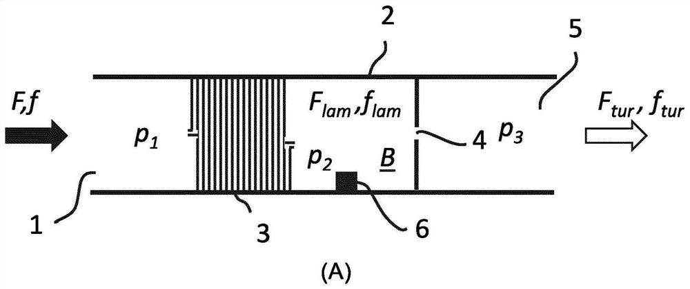
[0081] figure 1 shows how the fluid F, f at the first pressure p 1 Down through the fluid inflow port 1 into the conduit 2, further through the first fluid flow restrictor 3 and into chamber B where it reaches the second pressure p 2 , and then flow through the second fluid flow restrictor 4, and then at the third pressure p 3 down through the fluid outflow port 5 out of the conduit 2 . When the fluid flow rate and fluid properties (such as viscosity, density) are kept constant, the pressure (p 1 ,p 2 ,p 3 ) is also constant, and p 1 ,>p 2 ,>p 3 .

[0082] exist figure 1 In , the first fluid flow restrictor 3 is a helical tube, and the second fluid flow restrictor 4 is an orifice. The helical tube can have any cross-sectional shape, such as circular, rectangular, triangular, etc.

[0083] In general, the pressure loss due to viscosity in a cylindrical tube of length L and diameter D is proportional to the length L and can be expressed by the Darcy-Weisbach equation ...


PUM


Abstract

It is provided a fluid flow control device for establishing a controllable fluid communication between an external fluid reservoir and a base pipe constituting part of a production string, as well asa production string and a method using such fluid flow control device. The fluid flow control device comprises a primary flow path arranged inside a fluid control device housing, a secondary flow pathand a movable valve element arranged at and / or within the primary flow path. The inlet of the secondary flow path is arranged to be separated from the inlet of the primary flow path.

Description

technical field [0001] The present invention relates to the control of fluid flow into catheters. More particularly, the present invention relates to a fluid flow control device, as well as subsea production strings and methods of using such a fluid flow control device. The present invention can be used to control fluid flow from a subterranean hydrocarbon reservoir to a production string. Background technique [0002] A well for producing hydrocarbons from a subterranean reservoir may extend in multiple directions through the reservoir. Traditionally, reservoirs have been accessed by drilling vertical wells. This is a simple and straightforward technique, but each well has limited reservoir exposure. Therefore, in order to gain access to more reservoirs in each well, techniques and devices have been developed for drilling horizontal wells, ie turning the wells from vertical to horizontal at a predetermined depth below the earth's surface. So-called multilateral wells pr...

Claims


Application Information

Patent Timeline
Patent Type & Authority Applications(China)
IPC IPC(8): E21B34/08E21B43/12G05D7/01
CPCE21B34/08E21B43/12G05D7/012F15D1/025F16K15/14G05D7/0133E21B43/32F16K31/1221
Inventor 维达·马蒂森哈瓦尔德·阿克雷比约纳·威尔斯维克
Owner INFLOWCONTROL
Why Eureka
Try Eureka