Medical injector detection device

A technology for detection devices and syringes, which is applied in the direction of measuring devices, testing of machines/structural components, instruments, etc., can solve problems such as easy shaking of syringes, non-standard pulling movements, and inaccurate parameters, so as to improve the speed of detection operations and improve The effect of reference value

Active Publication Date: 2020-11-20
青海省药品检验检测院
View PDF6 Cites 0 Cited by
  • Summary
  • Abstract
  • Description
  • Claims
  • Application Information

AI Technical Summary

Problems solved by technology

[0004] The purpose of this invention is to solve the defects in the prior art that the pulling action is not standard and the syringe is easy to shake, which leads to inaccurate parameters and difficult collection, and proposes a medical syringe detection device

Method used


Image

  • Medical injector detection device
  • Medical injector detection device
  • Medical injector detection device

Examples


Embodiment 1

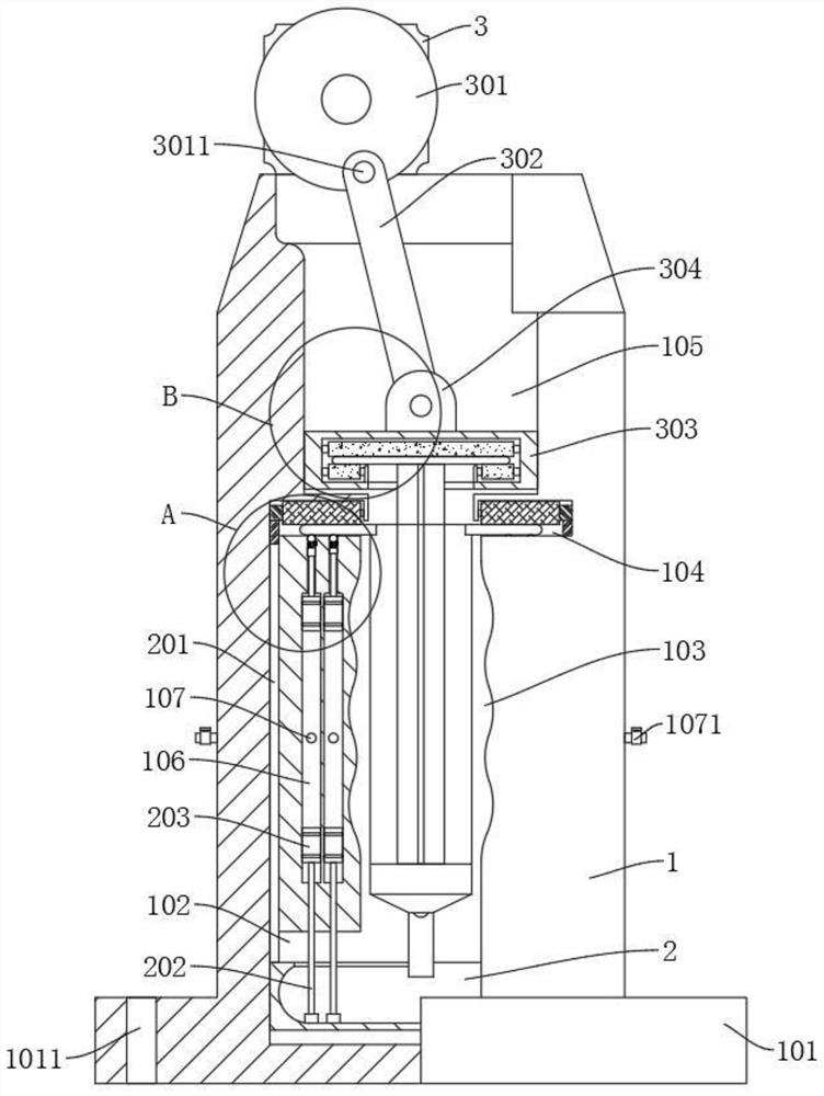
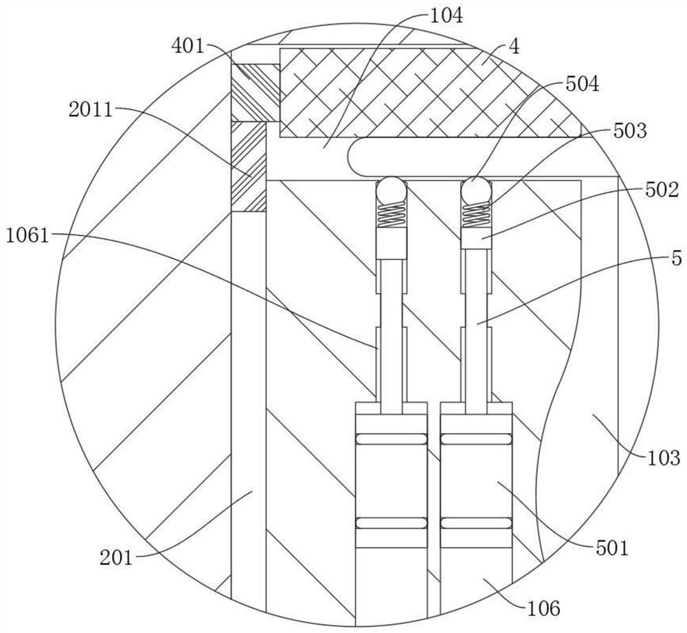
[0028] refer to Figure 1-4 , a medical syringe detection device, including a base 1 and a drive motor 3 fixedly connected to the top of the base 1, the base 1 is sequentially provided with a first sliding cavity 102, a through groove 103, a positioning cavity 104 and a second Two sliding chambers 105, the first sliding chamber 102 is slidably connected with the liquid storage box 2, the top of the positioning chamber 104 is rotatably connected with the driving wheel 4, the bottom of the positioning chamber 104 is rotatably connected with the ball 504, and the second sliding chamber 105 is slidably connected with the card Disk 303, a clamping cavity 3033 is opened in the chuck 303, and the clamping cavity 3033 is connected with the first clamping roller 3031 and the second clamping roller 3032 in sequence from top to bottom, and the top of the chuck 303 is fixedly connected with a rotating seat 304 , the output end of the drive motor 3 is fixedly connected to the turntable 301...

Embodiment 2

[0031] refer to figure 1 and image 3, which is basically the same as that of Embodiment 1, furthermore, an air storage cavity 106 is opened in the base 1, an exhaust pipe 107 is provided on the air storage cavity 106, and a valve 1071 is provided on the exhaust pipe 107 extending to the outside of the base 1 , the liquid storage box 2 is fixedly connected with the second telescopic rod 202, the top of the second telescopic rod 202 is fixedly connected with the second piston 203, the second piston 203 is slidably connected with the bottom of the gas storage chamber 106, and the top of the gas storage chamber 106 has a limited position Cavity 1061, the limit chamber 1061 is slidingly connected with the first telescopic rod 5, and the two ends of the first telescopic rod 5 are respectively fixedly connected with the top block 502 and the first piston 501, and the first piston 501 is slidably connected in the air storage chamber 106 , the top of the limiting cavity 1061 communic...

Embodiment 3

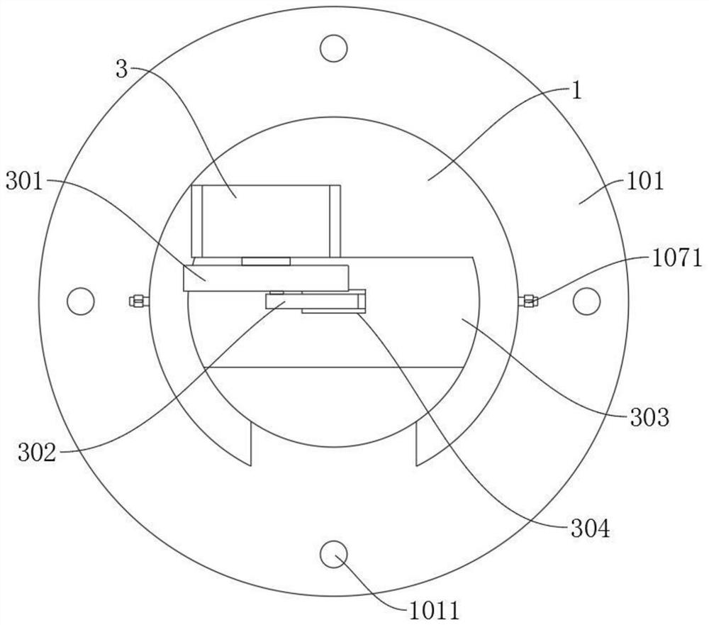
[0034] refer to Figure 1-2 and Figure 4 , which is basically the same as that of Embodiment 1, and furthermore, the material of the first pinch roller 3031 and the second pinch roller 3032 is rubber, and the bottom of the base 1 is fixedly connected with a positioning plate 101, and the positioning plate 101 is uniform in circumference. There are positioning holes 1011. During use, the clamping roller made of rubber has partial deformation ability, which can not only effectively clamp the piston handle of the syringe, but also facilitate access. Before use, fix the positioning plate 101 on the On the workbench, prevent shaking during detection and improve the accuracy of detection data.


PUM


Abstract

The invention discloses a medical injector detection device, and belongs to the technical field of medical equipment production instruments. The medical injector detection device comprises a base anda driving motor connected to the top of the base. A first sliding cavity, a through groove, a positioning cavity and a second sliding cavity are formed in the base. A liquid storage box slides in thefirst sliding cavity. A driving wheel and a ball body are rotationally connected in the positioning cavity. A chuck is slidably connected into the second sliding cavity. A clamping cavity is formed inthe chuck, a first clamping roller and a second clamping roller are sequentially and rotationally connected to the clamping cavity from top to bottom, a rotating base is connected to the top of the chuck, a rotating disc is connected to the output end of the driving motor, an eccentric shaft is connected to the rotating disc, a connecting rod is rotationally connected to the eccentric shaft, andthe end, away from the eccentric shaft, of the connecting rod is rotationally connected to the rotating base. According to the invention, the action of manual use of the injector is simulated more truly by using the quick-return characteristic, so that the acquired data is more suitable for various parameters during actual manual use, and the reference value of the acquired data is improved.

Description

technical field [0001] The invention relates to the technical field of medical equipment production equipment, in particular to a medical syringe detection device. Background technique [0002] A syringe is a common medical device. The syringe barrel can be made of plastic or glass. The syringe consists of a piston, a piston handle, an empty barrel, and a nipple, and usually has a scale indicating the volume of liquid in the syringe. Glass syringes can be sterilized with an autoclave, but because the processing cost of plastic syringes is low, most modern medical syringes are made of plastic. For defects, it is necessary to conduct sampling inspections on the syringes on time. [0003] In the existing technology, the detection method is mostly mechanical rigid pulling detection, and the detected data is difficult to fit the actual use of the pulling action, and the syringe shakes and deviates greatly during the pulling process, causing the syringe to The reference value o...

Claims


Application Information

Patent Timeline
Patent Type & Authority Applications(China)
IPC IPC(8): G01M99/00
CPCG01M99/00
Inventor 陈岳蓉程小平孙晓宁
Owner 青海省药品检验检测院
Why Eureka
Try Eureka