
Intelligent turntable for testing electrical performance of radome

A kind of radome and intelligent technology, which is applied to the parts of electrical measuring instruments, measuring electricity, measuring devices, etc., can solve the problems of inability to achieve fully automated measurement of radomes, inaccurate test results, and potential safety hazards, and achieve intelligent test, realize process operation, and ensure the effect of consistency

Pending Publication Date: 2020-11-20
THE RES INST FOR SPECIAL STRUCTURES OF AERONAUTICAL COMPOSITE AVIC
View PDF3 Cites 0 Cited by
  • Summary
  • Abstract
  • Description
  • Claims
  • Application Information

AI Technical Summary

Problems solved by technology

[0004] Using the existing test turntable structure, every time a state is measured, it is necessary to manually mount and unload the radome on a higher platform, which not only presents the danger of high altitude, but also takes time and effort. When the radome is frequently installed and unloaded, labor The strength is extremely high. During the test process, testers need to pay attention to whether a certain test state is completed and the next state has been measured. Therefore, the traditional turntable measurement technology cannot achieve fully automated measurement of radome.
During manual assisted measurement, on the one hand, there are potential safety hazards, and on the other hand, due to the existence of testers’ subjective factors, the test results are inaccurate

Method used


Image

  • Intelligent turntable for testing electrical performance of radome
  • Intelligent turntable for testing electrical performance of radome
  • Intelligent turntable for testing electrical performance of radome

Examples


Embodiment Construction

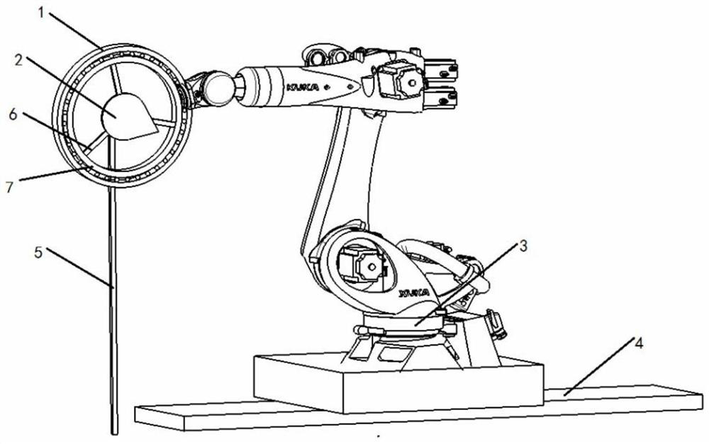
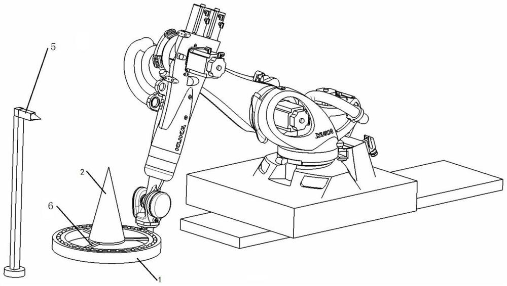
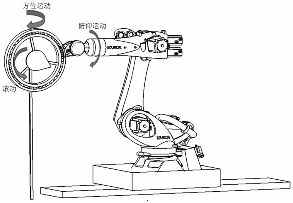
[0016] In the present invention, a new type of intelligent turntable is designed. The structure of the turntable is transformed by an industrial robot, and the measurement function of the radome can be realized through the movement of the robot itself. The structure of the turntable is as follows: figure 1 shown. The intelligent turntable is composed of a base, a slide rail, an azimuth rotation shaft, an azimuth turntable, a pitch support arm, a pitch rotation shaft, a pitch ring, a circular motion mechanism, a radome fixer, and an antenna pole; the slide rail is arranged on the base, There are pins at both ends of the guide rail to prevent the movement limit state from leaving the base; the azimuth shaft cooperates with the slide rail, on the one hand, it can move along the slide rail, and on the other hand, it can rotate itself; the pitch support arm is installed on the azimuth turntable, and the azimuth turntable It can rotate 360° around the azimuth shaft; the pitch ring i...


PUM


Abstract

The invention discloses an intelligent turntable for testing the electrical performance of a radome. The intelligent turntable consists of a base, a sliding rail, an azimuth rotating shaft, an azimuthturntable, a pitching support arm, a pitching rotating shaft, a pitching ring, an annular motion mechanism, a radome fixator and an antenna supporting rod, wherein the sliding rail is arranged on thebase, the azimuth rotating shaft is matched with the sliding rail, and on the one hand, the azimuth rotating shaft can move along the sliding rail, and on the other hand, the azimuth rotating shaft rotates; the pitching support arm is mounted on the azimuth turntable, and the azimuth turntable can rotate by 360 degrees around the azimuth rotating shaft; the pitching ring is arranged on the pitching support arm and is connected with the pitching rotating shaft arranged on the pitching support arm, and the pitching ring can pitch upwards or downwards around the pitching rotating shaft; the annular motion mechanism is sleeved with the pitching ring, the annular motion mechanism can rotate around the axis of the pitching ring, and the radome fixator is connected to the annular motion mechanism and used for supporting the radome; one end of the antenna supporting rod is supported on the ground platform, and the other end passes through the radome fixator to support the test antenna in theradome.

Description

technical field [0001] The invention belongs to the technical field of radome testing equipment, and relates to an intelligent turntable for radome electrical performance testing. Background technique [0002] When the radome is installed on the turntable for measurement, it is necessary to simulate the movement state of the antenna in the radome through the azimuth movement, pitch movement, rolling along the central axis of the radome, and forward and backward movement of the turntable, and measure the electric current in each state. performance parameters. The traditional radome test turntable is generally a four-axis turntable, which has the functions of azimuth scanning, pitch scanning, rolling and forward and backward movement. [0003] The turntable realizes the upward or downward movement of the radome through the pitch ring. The rolling ring is located inside the pitch ring, which can realize the rotation of the radome around the central axis. The receiving antenna ...

Claims


Application Information

Patent Timeline
Patent Type & Authority Applications(China)
IPC IPC(8): G01R1/04G01R31/00
CPCG01R1/0408G01R31/00
Inventor 李传兰刘尚吉许群
Owner THE RES INST FOR SPECIAL STRUCTURES OF AERONAUTICAL COMPOSITE AVIC
Learn More