Unlock instant, AI-driven research and patent intelligence for your innovation.

Method of simulating vehicle starting power supply

A technology that simulates vehicles and starts the power supply. It is applied to the parts of electrical measuring instruments, measuring electricity, measuring electrical variables, etc., and can solve the problem of unable to find power supply jitter.

Pending Publication Date: 2020-11-20
嘉兴行适安车联网信息科技有限公司
View PDF9 Cites 0 Cited by
  • Summary
  • Abstract
  • Description
  • Claims
  • Application Information

AI Technical Summary

Problems solved by technology

[0002] When testing vehicle-mounted products on the office bench, the DC power supply is supplied, and the voltage is relatively stable, but on the real vehicle, there will be power jitter when the vehicle is started, so the bench test cannot Some problems caused by power jitter when using the real car

Method used


Image

  • Method of simulating vehicle starting power supply

Examples


no. 1 example

[0041] First embodiment (preferred embodiment).

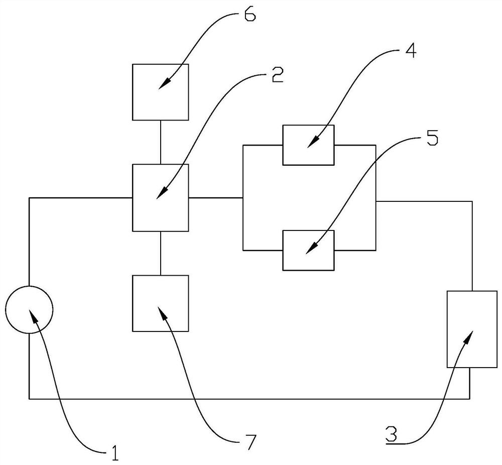
[0042] The invention discloses a method for simulating a starting power supply of a vehicle, which is used for simulating the power supply jitter generated when the vehicle starts, comprising the following steps:

[0043] Step S1: the DC power supply 1, the control module 2 and the device under test 3 are electrically connected in sequence to form a loop;

[0044] Step S2: connecting the first relay 4 and the second relay 5 between the control module 2 and the device under test 3 and connecting the first relay 4 and the second relay 5 in parallel;

[0045] Step S3: the first relay 4 and the second relay 5 perform cycle switching at different frequencies;

[0046] Step S4: The control module 2 monitors the first relay 4, the second relay 5 and the device under test 3 respectively.

[0047] Specifically, step S3 is specifically implemented as the following steps:

[0048] Step S3.1: the first relay 4 performs cycle switching a...

no. 2 example

[0069] The invention discloses a method for simulating a starting power supply of a vehicle, which is used for simulating the power supply jitter generated when the vehicle starts, comprising the following steps:

[0070] Step S1: the DC power supply 1, the control module 2 and the device under test 3 are electrically connected in sequence to form a loop;

[0071] Step S2: connecting the first relay 4 and the second relay 5 between the control module 2 and the device under test 3 and connecting the first relay 4 and the second relay 5 in parallel;

[0072] Step S3: the first relay 4 and the second relay 5 perform cycle switching at different frequencies;

[0073] Step S4: The control module 2 monitors the first relay 4, the second relay 5 and the device under test 3 respectively.

[0074] Specifically, step S3 is specifically implemented as the following steps:

[0075] Step S3.1: the first relay 4 performs cycle switching at the first frequency;

[0076] Step S3.2: The sec...


PUM


Abstract

The invention discloses a method for simulating a vehicle starting power supply. The method comprises the steps that S1, a direct-current power supply, a control module and a to-be-tested device are electrically connected in sequence to form a loop; S2, a first relay and a second relay are connected between the control module and the to-be-tested device, and the first relay and the second relay are connected in parallel; S3, the first relay and the second relay are circularly opened and closed at different frequencies; and S4, the control module monitors the first relay, the second relay and the to-be-tested device. According to the method for simulating a vehicle starting power supply disclosed by the invention, the bench test power supply achieves the effect of vehicle power supply jitter through simple operation of assessing the relays into the circuit, so that some problems caused by power supply jitter of a vehicle-mounted product on a real vehicle can be discovered in time.

Description

technical field [0001] The invention belongs to the technical field of vehicle power supply simulation, and in particular relates to a method for simulating a vehicle starting power supply. Background technique [0002] The office bench test vehicle products are powered by a DC power supply, and the voltage is relatively stable, but on the real car, there will be power jitter when the vehicle is started, so the bench test cannot find some problems caused by the power jitter when the real car is used. [0003] The publication number is: CN104057951A, the subject name is an invention patent of an intelligent start-stop micro-mixing system and its control method, and its technical solution discloses "including a data processing single-chip microcomputer, which is connected to the ECU of the car through the CAN bus, and connected to the data processing An analog signal input control module for the single-chip microcomputer to perform data communication, the analog signal input c...

Claims


Application Information

Patent Timeline
IPC IPC(8): G01R1/28G01R31/00
CPCG01R1/28G01R31/00
Inventor 吴亚南
Owner 嘉兴行适安车联网信息科技有限公司