Automatic reflection light path adjusting assembly, adjusting device and using method
A technology of reflecting optical path and adjusting components, which is applied in the direction of optical components, installation, optics, etc., can solve the problems of inconvenient overall adjustment and less dimension of attitude adjustment, and achieve the effect of stable and reliable adjustment process, simple and firm circuit, and high reliability
- Summary
- Abstract
- Description
- Claims
- Application Information
AI Technical Summary
Problems solved by technology
Method used
Image
Examples
Embodiment 1
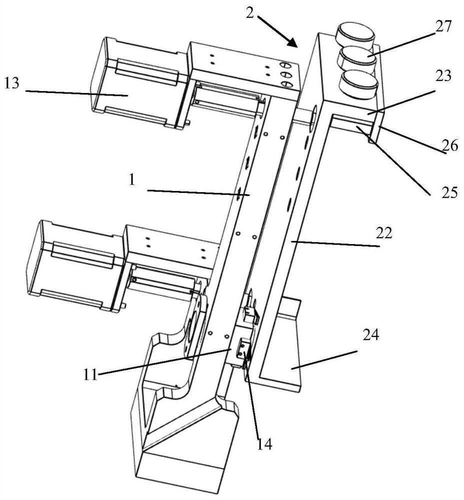
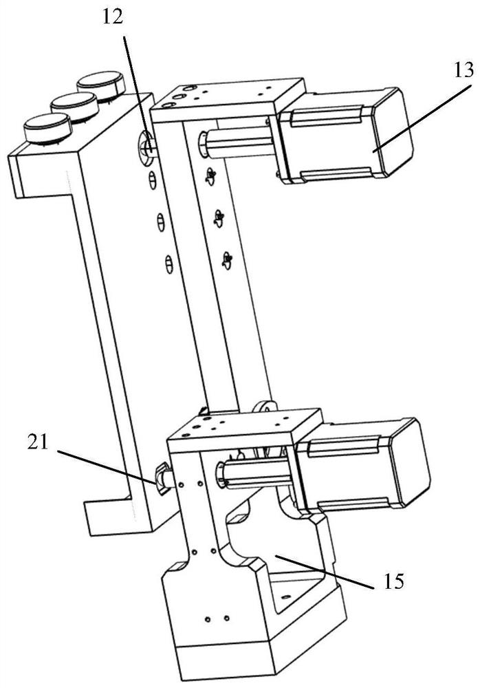
[0037] An automatic reflection optical path adjustment assembly of the present invention includes a base plate 1 and an adjustment plate 2 loaded with reflective lenses, wherein the adjustment plate is fixed on the base plate and is driven to rotate around a fixed point 11 relative to it. Two adjusting push rods 12 that are driven to extend or retreat are arranged on the base plate of the base plate, and a tension spring (not shown in the figure) is arranged between the base plate and the adjusting plate to make the ends of the adjusting push rods consistent with the adjustment The top of the board back fits snugly. There can be one or several extension springs, and they can be arranged adjacent to the adjusting push rod or arranged in each area respectively.
[0038] Specifically, the base plate is fixed vertically, the adjusting plate is fixed substantially vertically or substantially vertically in front of the base plate, and the two are fixedly connected at the middle or o...
Embodiment 2
[0043] The adjustment plate of the present invention includes a back plate 22, an upper positioning plate 23 and a lower positioning plate 24 formed on the upper and lower ends of the front surface of the back plate, and a clamping plate arranged on the inner side of the upper positioning plate and driven to move downward to clamp the reflector 25. At the same time, an upper lintel 26 covering the clamping plate is arranged on the front of the upper positioning plate, and the clamping plate is tightened downward by the adjustment knob 27 screwed to the upper positioning plate Realize the clamping of the mirror.
[0044] The previous adjustment plate can only be adapted to a single type of lens, but the one in the present invention can match lenses of different widths. Moreover, the lens of the previous adjustment plate can only be installed at the front, and the lens is put into the fixed groove from the front, and then the lens is pressed by the pressing pieces on both sides,...
Embodiment 3
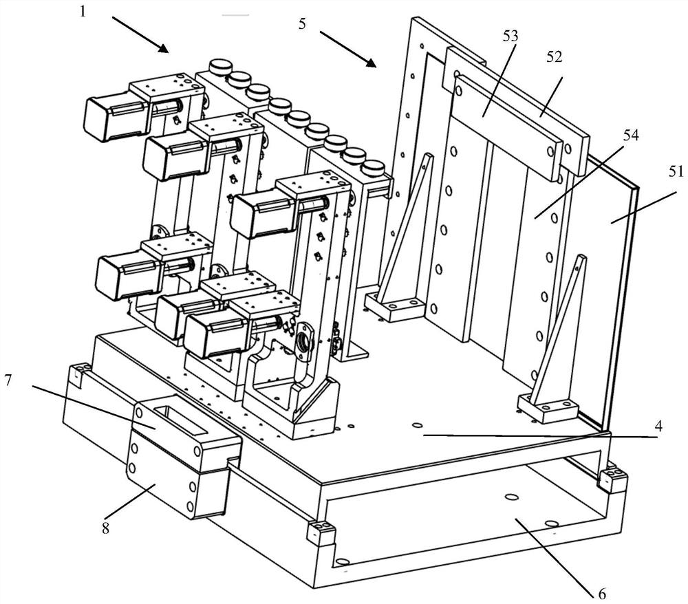
[0046]The invention discloses an automatic reflection optical path adjustment device, which includes a fixing part used to be fixedly connected with an optical platform and a detachable transfer part that can be matched with the fixing part and correspondingly connected and positioned, and the transfer part includes its There are a large number of threaded holes above which can install the transfer plate 4 of different components, corresponding to the described adjustment components fixedly arranged on the transfer plate.
[0047] Generally speaking, depending on the situation, an adjustment assembly, or two or more adjustment assemblies arranged side by side are arranged on the transfer plate, which is determined according to the number of optical paths, and the optical path adjustment devices are installed in pairs. The reflection between two opposite adjustment devices forms a reflection optical path, so for a single-side optical path adjustment device, an adjustment compone...
PUM
 Abstract
Description
Claims
Application Information
 - R&D
- Intellectual Property
- Life Sciences
- Materials
- Tech Scout
- Unparalleled Data Quality
- Higher Quality Content
- 60% Fewer Hallucinations
Browse by: Latest US Patents, China's latest patents, Technical Efficacy Thesaurus, Application Domain, Technology Topic, Popular Technical Reports.
© 2025 PatSnap. All rights reserved.Legal|Privacy policy|Modern Slavery Act Transparency Statement|Sitemap|About US| Contact US: help@patsnap.com


