A compact radar antenna turntable

A radar antenna, compact technology, applied in the directions of antenna, antenna support/installation device, electrical components, etc., can solve the problem of small size of radar antenna turntable, and achieve the effect of compact structure, small volume and good locking effect

Active Publication Date: 2022-07-29
XIAN AEROSPACE PRECISION ELECTROMECHANICAL INST
View PDF10 Cites 0 Cited by
  • Summary
  • Abstract
  • Description
  • Claims
  • Application Information

AI Technical Summary

Problems solved by technology

[0003] The purpose of the present invention is to solve the problem that the radar antenna turntable existing in the prior art is difficult to satisfy the problem of small size, light weight, and portability, and provides a compact radar antenna turntable

Method used


Image

  • A compact radar antenna turntable
  • A compact radar antenna turntable
  • A compact radar antenna turntable

Examples


Embodiment Construction

[0064] In order to make the objectives, advantages and features of the present invention clearer, a compact radar antenna turntable proposed by the present invention will be described in further detail below with reference to the accompanying drawings and specific embodiments.

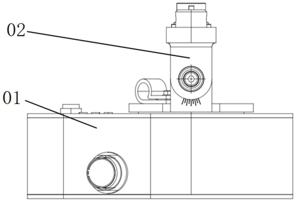
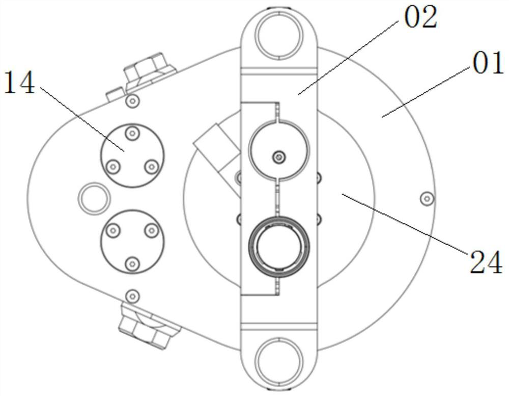
[0065] like figure 1 , figure 2 As shown, the compact radar antenna turntable provided by the present invention includes an azimuth adjustment unit 01 and a pitch adjustment unit 02 .

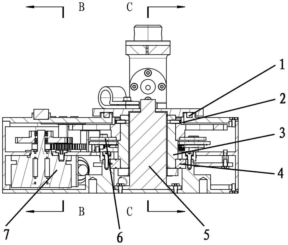
[0066] like image 3 As shown, the azimuth adjustment unit 01 includes a casing, a disc motor 7 , a gear transmission mechanism, an output flange 3 , a confluence ring 5 , and an encoder 6 .

[0067] The disc motor 7 and the gear transmission mechanism are located in the housing. The gear transmission mechanism includes a driving gear 8, a speed change gear assembly and a driven gear 11. The drive gear 8 is fixedly installed on the output shaft of the disc motor 7, and is connected with the transmission gear assembly...


PUM


Abstract

The invention relates to a compact radar antenna turntable, comprising an azimuth adjustment unit and a pitch adjustment unit. The azimuth adjustment unit includes a casing, a disc motor, a gear transmission mechanism, an output flange, a manifold ring, and an encoder; the gear transmission mechanism includes a driving gear, a variable speed gear assembly, and a driven gear, and the driving gear is fixedly installed on the output shaft of the disc motor. It is connected with the driven gear through the speed change gear assembly. The driven gear is fixedly sleeved on the outside of the output flange, the lower end of the output flange is rotatably connected with the outer casing, the upper end extends out of the outer casing, and the confluence ring is arranged in the hollow of the output flange. In the cavity, the encoder moving plate is fixedly connected with the lower surface of the driven gear. The pitch adjustment unit includes a support base, a pitch axis, a clamp for installing the radar antenna, and a locking mechanism; the support base is fixedly installed on the upper end of the output flange, and both ends of the clamp are hinged to the support base through the pitch axis, and the locking mechanism is used for In the pitch attitude of the fixed hoop.

Description

technical field [0001] The invention relates to a compact radar antenna turntable. Background technique [0002] Radar antenna turntables are often used in field surveying and mapping equipment to complete accurate target tracking and data measurement by driving the radar antenna to adjust the attitude. The radar antenna turntable generally requires small size, light weight, low energy consumption, and high positioning accuracy. At the same time, in order to adapt to the harsh weather conditions in the field, the turntable also needs to have strong anti-overturning ability and high protection level, and has the ability to be compatible with other equipment (antenna, tripod) interface for quick installation. Patent CN 109149111A discloses a direct-drive radar turntable, which adopts the method of directly driving the output shaft of a torque motor. The structure is relatively simple, but it is difficult to meet the requirements of the portable turntable on size, weight and p...

Claims


Application Information

Patent Timeline
Patent Type & Authority Patents(China)
IPC IPC(8): H01Q1/12H01Q3/08
CPCH01Q1/12H01Q3/08
Inventor 王超朱美俊苟义龙岳盼薇米乾宝顾鹏郭佳赟樊峰宇赵哲
Owner XIAN AEROSPACE PRECISION ELECTROMECHANICAL INST
Why Eureka
Try Eureka