
Pmos power tube gate clamp drive module, drive circuit and switching power supply

A drive module and gate drive technology, which is applied in the direction of high-efficiency power electronic conversion, output power conversion device, DC power input conversion to DC power output, etc., can solve the problem of large switching loss and the gate and source of PMOS transistors. Effective clamping, affecting conversion efficiency and other issues, to achieve the effect of reducing conduction loss

Active Publication Date: 2021-01-15
SHANGHAI XINLONG SEMICON TECH CO LTD
View PDF4 Cites 0 Cited by
  • Summary
  • Abstract
  • Description
  • Claims
  • Application Information

AI Technical Summary

Problems solved by technology

[0005] Due to the parasitic capacitance between the gate and the source (there is a parasitic capacitance between the gate and the source of the MOS transistor, when the PMOS power transistor is to be turned on, it is necessary to charge the parasitic capacitance between the gate and the source of the PMOS power transistor, and the charging time The shorter the PMOS tube is, the faster the turn-on speed of the PMOS tube is; when the PMOS power tube is to be turned off, the parasitic capacitance between the gate and the source of the PMOS power tube needs to be discharged, the shorter the discharge time, the faster the PMOS tube is turned off). When the power tube is turned on and off, there will be switching loss of the MOS power tube (the loss of the power tube at the moment of turning on and off is called switching loss). The switching loss of the power tube is related to the speed of turning on and off of the power tube. The PMOS gate drive scheme cannot quickly turn on and off the PMOS tube, resulting in relatively large switching losses and affecting the conversion efficiency. At the same time, it cannot effectively clamp the gate and source of the PMOS tube. Generally, it can only be used for low power within 40V. In switching power supplies, the application is limited

Method used


Image

  • Pmos power tube gate clamp drive module, drive circuit and switching power supply
  • Pmos power tube gate clamp drive module, drive circuit and switching power supply
  • Pmos power tube gate clamp drive module, drive circuit and switching power supply

Examples


Embodiment Construction

[0029] In order to facilitate the understanding of those skilled in the art, the present invention will be further described in detail below in conjunction with specific embodiments.

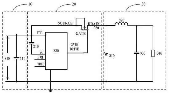
[0030] The embodiment of the present invention firstly provides a switching power supply, please refer to figure 1 , including a power supply circuit 10 , an output circuit 30 and a switching power supply driving circuit 20 . One end of the switching power supply driving circuit 20 is connected to the power supply circuit 10 , and the other end of the switching power supply driving circuit 20 is connected to the output circuit 30 .

[0031] In this embodiment, the power supply circuit 10 includes an input DC power supply VIN and an input filter capacitor 110 connected in parallel.

[0032] The output circuit 30 includes a Schottky diode 310, a power inductor 320, an output filter capacitor 330, and a load 340. The cathode of the Schottky diode 310 is connected to the drain of the PMOS power tra...


PUM


Abstract

The invention provides a PMOS power tube gate clamp drive module, a drive circuit and a switching power supply. By externally connecting an energy storage capacitor to the clamp power supply, the clamp power supply can charge the energy storage capacitor with a small current, and the PMOS can be turned on when needed. When the power tube is used, the power in the energy storage capacitor is used to charge the gate-source parasitic capacitance in a short time, so that the clamp power supply circuit can quickly charge the large gate-source parasitic capacitance through small current output. By quickly turning on and off the power tube, it solves the large turn-on and turn-off losses of the PMOS power tube in the switching power supply chip, and at the same time controls the voltage difference between the gate voltage and the source voltage at -9V, further reducing the PMOS tube conduction. pass loss.

Description

[0001] PMOS power transistor gate clamp drive module, drive circuit and switching power supply technical field [0002] The invention relates to the field of switching power supplies, in particular to a PMOS power transistor grid clamp drive module, a switching power supply drive circuit and a switching power supply. Background technique [0003] The power tube inside the switching power supply chip has two types: power triode and power MOS tube. The power MOS tube is divided into PMOS power tube and NMOS power tube. For the step-down (BUCK) chip, PMOS tube is selected as the control circuit of the switch tube. It is completely different from the control circuit that chooses NMOS tube as the switch tube. [0004] For common MOS transistors, the withstand voltage between the drain and the source can be 80V, 100V or even greater, but the withstand voltage of the gate and source of the MOS transistor is limited by the process and cost, and it is generally controlled at + / - Wit...

Claims


Application Information

Patent Timeline
Patent Type & Authority Patents(China)
IPC IPC(8): H02M1/08H02M3/157
CPCH02M1/08H02M3/157H02M1/0054Y02B70/10
Inventor 李瑞平池伟刘彬吕战辉
Owner SHANGHAI XINLONG SEMICON TECH CO LTD
Learn More