
Oven device

A kind of oven and furnace furnace technology, which is applied in the direction of roaster/barbecue grid, kitchen utensils, household utensils, etc. It can solve the problems of cumbersome and time-consuming procedures, difficult oil residue removal, and insulation cotton filling dead corners, etc., to solve the difficulty of assembly , to achieve real-time monitoring, to prevent the effect of overheating

Inactive Publication Date: 2020-11-24
马鞍山骋运博精密机械有限责任公司
View PDF0 Cites 0 Cited by
  • Summary
  • Abstract
  • Description
  • Claims
  • Application Information

AI Technical Summary

Problems solved by technology

[0002] With the improvement of the quality of daily life, people have higher requirements for the taste of food, especially baked food, and general restaurants and food factories will use large ovens, because generally large ovens have been used for a long time There will be a layer of oil residue on the surface, and it is difficult to remove the oil residue on the stainless steel surface of ordinary large-scale ovens. If it is not cleaned for a long time, it will affect the sanitation of the entire production environment
[0003] At present, the stainless steel casing used in general large-scale ovens must be bent, assembled and fixed by welding during the installation process of the casing components, and then welded by a welding machine. After welding, the furnace of the oven is assembled, and the furnace is assembled. After the completion, fill the insulation cotton. This method will cause the insulation cotton to fill the dead space, which will affect the insulation effect. Since the furnace is assembled after the box is fixed, the difficulty of furnace assembly is increased. At the same time, professional technicians are required for welding. The whole process is cumbersome and time-consuming, which is not conducive to the requirements of modern high-speed production industry

Method used


Image

  • Oven device
  • Oven device

Examples


Embodiment

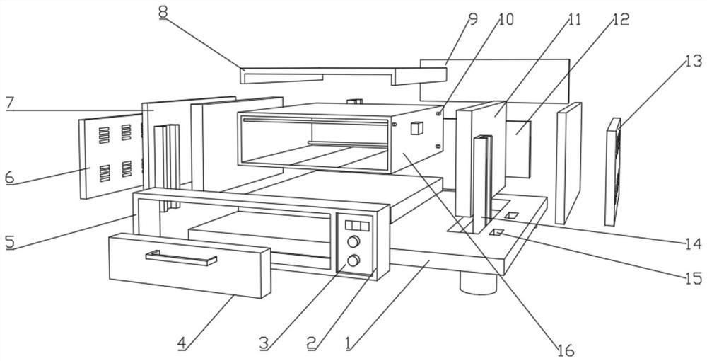
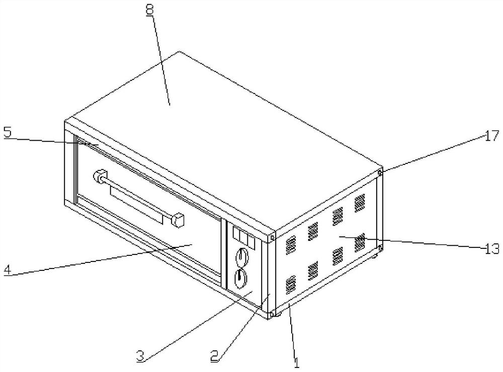
[0018] Example: such as Figure 1-2 As shown, an oven device of the present invention comprises a base 1, a furnace 16 and a heating pipe 10, one side of the base 1 is provided with a furnace door frame 5, and both sides of the furnace door frame 5 are provided with edge guards 2, and the edge guards 2 Screw holes 17 are provided on the top side of the furnace, and the edge guard rod 2 is fixedly connected with the furnace door frame 5 by screws. One side of the furnace door frame 5 is provided with an adjustment panel 3, and the top side of the adjustment panel 3 is provided with a temperature display, and the adjustment panel 3 A circuit board is provided inside the furnace door frame 5, a furnace door panel 4 is provided on one side of the furnace door frame 5, a rock wool board 11 is provided on both sides of the base 1, a support plate 7 is provided on the outside of the rock wool board 11, and a support board 7 is provided on one side of the support board 7. There is a s...


PUM


Abstract

The invention provides an oven device. The device comprises a base, a furnace pipe and a heating pipe, a furnace door frame is arranged on one side of the base; edge protection rods are arranged on two sides of the furnace door frame; a screw hole is formed in one side of the top of the edge protection rod; the edge protection rods are fixedly connected with the furnace door frame through screws;an adjusting panel is arranged on one side of the furnace door frame; a temperature display is arranged on one side of the top of the adjusting panel; a circuit board is arranged in the adjusting panel; a furnace door plate is arranged on one side of the furnace door frame, rock wool plates are arranged on the two sides of the base, supporting plates are arranged on the outer sides of the rock wool plates, side sealing plate supporting frames are arranged on one sides of the supporting plates and connected with the supporting plates through arranged screws, fixing grooves are formed in the twoends of the top of the base, and the supporting plates are fixedly connected with the base through the fixing grooves. According to the oven device, the problems that the surface of the prepared whole body is uneven and the assembling difficulty is high due to welding are solved.

Description

technical field [0001] The invention relates to the technical field of an oven, in particular to an oven device. Background technique [0002] With the improvement of the quality of daily life, people have higher requirements for the taste of food, especially baked food, and general restaurants and food factories will use large ovens, because generally large ovens have been used for a long time There will be a layer of oil residue on the surface, and it is difficult to remove the oil residue on the stainless steel surface of ordinary large-scale ovens. If it is not cleaned for a long time, it will affect the sanitation of the entire production environment. [0003] At present, the stainless steel casing used in general large-scale ovens must be bent, assembled and fixed by welding during the installation process of the casing components, and then welded by a welding machine. After welding, the furnace of the oven is assembled, and the furnace is assembled. After the complet...

Claims


Application Information

Patent Timeline
Patent Type & Authority Applications(China)
IPC IPC(8): A47J37/06
CPCA47J37/0629A47J37/0664
Inventor 刘龙云杨小妹马梦醒俞雷李波
Owner 马鞍山骋运博精密机械有限责任公司
Features
  • Generate Ideas
  • Intellectual Property
  • Life Sciences
  • Materials
  • Tech Scout
  • Unparalleled Data Quality
  • Higher Quality Content
  • 60% Fewer Hallucinations
Learn More