Anti-winding safe sweeping robot

A sweeping robot and anti-winding technology, applied in the field of robots, can solve problems such as easy entanglement of brush rollers

Active Publication Date: 2020-11-24
浙江旺潮科技有限公司
View PDF5 Cites 1 Cited by
  • Summary
  • Abstract
  • Description
  • Claims
  • Application Information

AI Technical Summary

Problems solved by technology

[0005] The object of the present invention is to provide an anti-winding safe sweeping robot that can automati

Method used


Image

  • Anti-winding safe sweeping robot
  • Anti-winding safe sweeping robot
  • Anti-winding safe sweeping robot

Examples


Embodiment 1

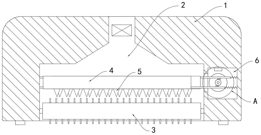
[0017] Such as Figure 1-2 As shown, an anti-winding safety sweeping robot includes a body 1, the lower surface of the body 1 is provided with a dust suction port 2, and a brush roller 3 arranged horizontally is arranged inside the dust suction port 2, and two blocks are arranged above the brush roller 3. Cutting plate 4, the lower ends of two cutting plates 4 are all arranged with cutting blades 5 equidistantly, and both sides of cutting blades 5 are provided with blades.

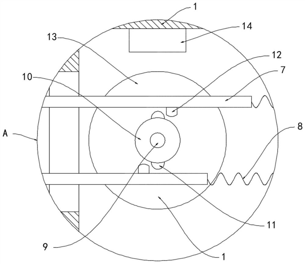
[0018] One side of the dust suction port 2 is provided with a drive cavity 6, and the ends of the two cutting plates 4 near the drive cavity 6 are fixedly connected with sliding rods 7, and the two sliding rods 7 are arranged in a staggered manner and both extend into the drive cavity 6. The sliding rods 7 are all fixedly connected with the inner sidewall of the drive chamber 6 by the return spring 8, and the drive chamber 6 is provided with a motor 9, which can slide vertically on the side wall of the dri...

Embodiment 2

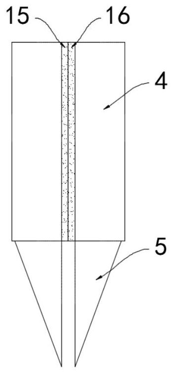
[0022] Such as image 3 As shown, the difference between this embodiment and Embodiment 1 is that the cutting blade 5 is made of metal conductive material, and the side walls of the two cutting plates 4 are respectively provided with a first friction plate 15 and a second friction plate 15. The friction plate 16, the first friction plate 15 is in contact with the second friction plate 16, the first friction plate 15 is a rubber plate, and the side wall of the second friction plate 16 close to the first friction plate 15 is attached with fur.

[0023] In this embodiment, the two cutting plates 4 drive the first friction plate 15 and the second friction plate 16 to undergo sliding friction during the staggered sliding process. According to the principle of frictional electricity generation, the rubber rod rubbed against the fur will carry a negative charge. , then the surfaces of the first friction plate 15 and the second friction plate 16 carry negative charges and positive cha...


PUM


Abstract

The invention belongs to the field of robots, and particularly relates to an anti-winding safe sweeping robot. The robot comprises a robot body, wherein a dust suction opening is formed in the lower surface of the machine body; a brush roller which is horizontally arranged is arranged in the dust suction opening; two cutting plates are arranged above the brush roller; cutting blades are arranged at the lower ends of the two cutting plates at equal intervals. A driving cavity is formed in one side of the dust suction opening; sliding rods are fixedly connected to the ends, close to the drivingcavity, of the two cutting plates; the two sliding rods are arranged in a staggered mode and extend into the driving cavity, the two sliding rods are fixedly connected with the inner side wall of thedriving cavity through reset springs, a motor is arranged in the driving cavity, a shifting wheel is coaxially installed on an output shaft of the motor, and two oppositely-arranged shifting blocks are fixedly connected to the side wall of the shifting wheel. The anti-winding safe sweeping robot can automatically and efficiently remove sundries such as hair and cotton fibers wound on the brush roller to guarantee the cleaning effect of the brush roller, thus avoiding the problems of motor burnout and the like caused by sundry winding.

Description

technical field [0001] The invention belongs to the field of robots, in particular to an anti-winding safe sweeping robot. Background technique [0002] With the improvement of people's living standards, sweeping robots are gradually replacing manual labor for household cleaning. The use of sweeping robots has greatly reduced people's labor intensity and facilitated people's rest in life. [0003] However, it is inevitable that hair and lint will fall on the ground in the home. During the cleaning process, traditional sweeping robots will suck and wind hair, lint and other debris on the brush roller, which will seriously affect the cleaning effect of the brush roller over time. When there are many sundries on the roller, it is very easy to cause deformation and bending of the brush roller, and even cause problems such as burning of the motor. Frequent cleaning is required, which is very inconvenient. [0004] To this end, we propose an anti-winding safe sweeping robot to so...

Claims


Application Information

Patent Timeline
IPC IPC(8): A47L11/24A47L11/40
CPCA47L11/24A47L11/40A47L11/4036A47L11/4041A47L11/4063A47L11/4069A47L2201/00
Inventor 张铭元
Owner 浙江旺潮科技有限公司
Why Eureka
Try Eureka