Parameter calibration method and parameter calibration device

A parameter calibration and coordinate system technology, applied in the medical field, can solve the problems of low precision, complex calculation, affecting the accuracy of ellipse fitting, etc., and achieve the effect of easy determination, simple process and accurate attitude information.

Active Publication Date: 2020-11-24
HANGZHOU SANTAN MEDICAL TECH
View PDF8 Cites 6 Cited by
  • Summary
  • Abstract
  • Description
  • Claims
  • Application Information

AI Technical Summary

Problems solved by technology

[0004] Since the steel balls arranged in a circle are arranged in an ellipse in the perspective image, too few steel balls will affect the accuracy of ellipse fitting, and too many steel balls will overlap in the perspective image and cause it to be unrecognizable
And using ellipse parameters to calculate the transformation relationship is an indirect way, and the calculation is relatively complicated and the accuracy is relatively low

Method used


Image

  • Parameter calibration method and parameter calibration device
  • Parameter calibration method and parameter calibration device
  • Parameter calibration method and parameter calibration device

Examples


Embodiment Construction

[0048] Reference will now be made in detail to the exemplary embodiments, examples of which are illustrated in the accompanying drawings. When the following description refers to the accompanying drawings, the same numerals in different drawings refer to the same or similar elements unless otherwise indicated. The implementations described in the following exemplary examples do not represent all implementations consistent with the present disclosure. Rather, they are merely examples of apparatuses and methods consistent with aspects of the present disclosure as recited in the appended claims.

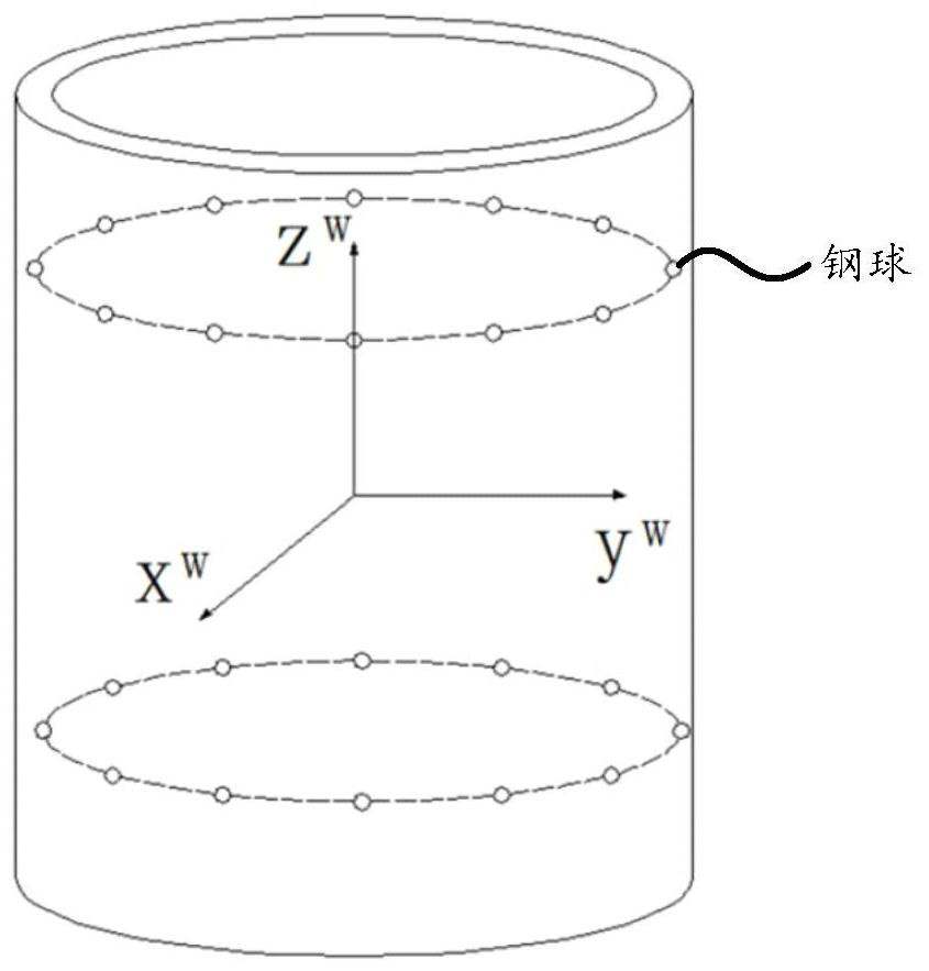
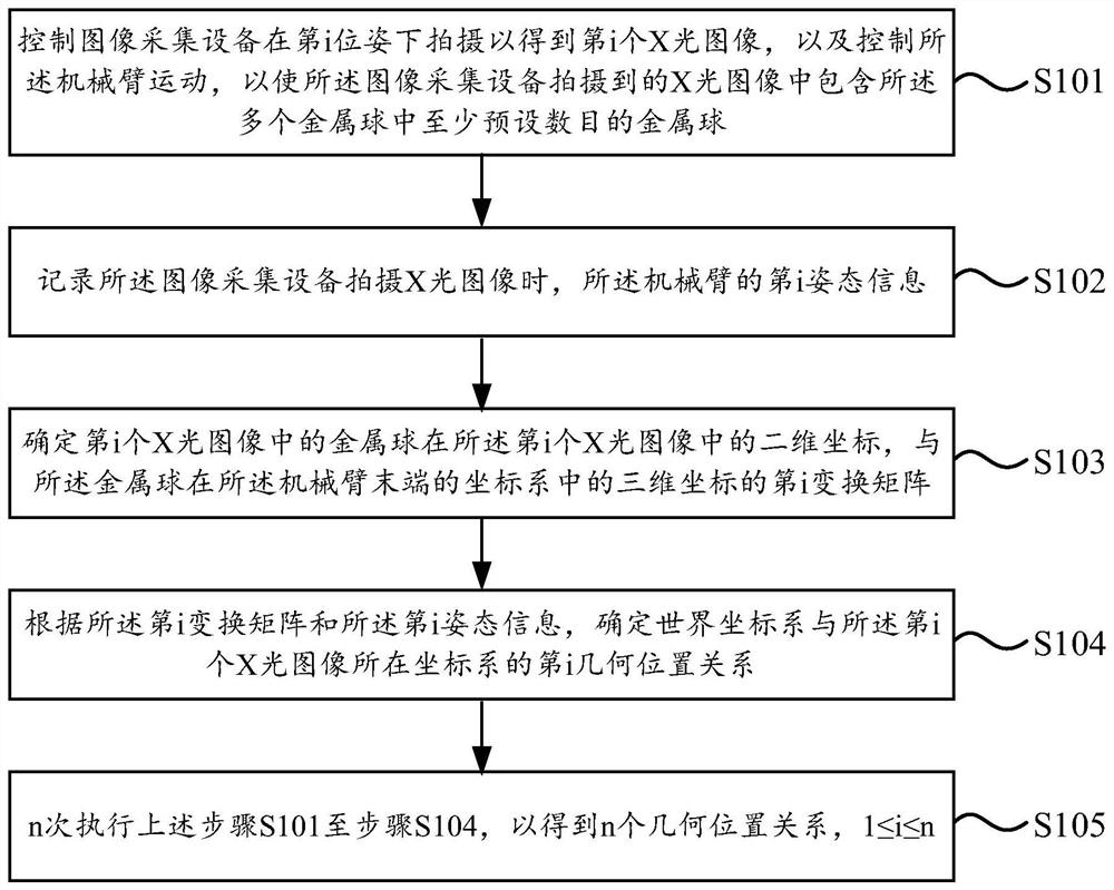
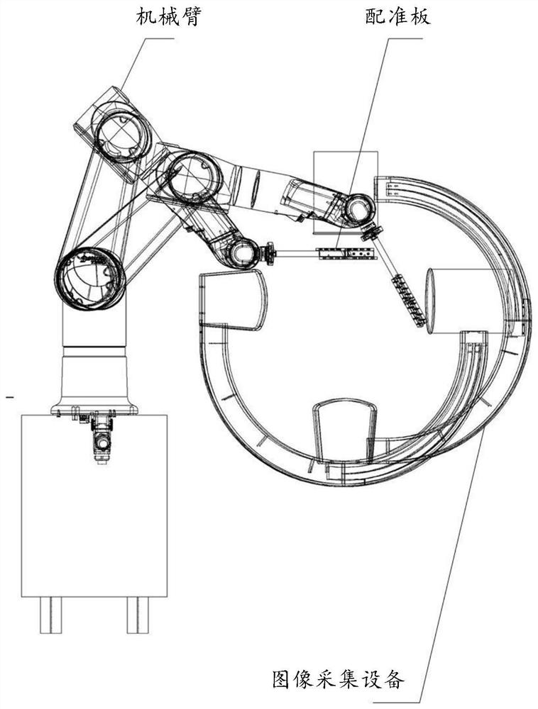
[0049] figure 2 is a schematic flowchart of a parameter calibration method shown according to an embodiment of the present disclosure. image 3 It is a schematic structural diagram of a parameter calibration system shown according to an embodiment of the present disclosure.

[0050] The method shown in this embodiment can be applied to a parameter calibration system, the parameter c...


PUM


Abstract

The invention relates to a parameter calibration method. The method comprises steps as follows: controlling image acquisition equipment to perform shooting in an ith pose to obtain an X-ray image, andcontrolling a mechanical arm to move to realize that the X-ray image shot by the image acquisition equipment contains at least the preset number of metal balls in multiple metal balls; recording ithpose information of the mechanical arm; determining two-dimensional coordinates of the metal balls in the X-ray image and an ith transformation matrix of three-dimensional coordinates of the metal balls in a coordinate system at the tail end of the mechanical arm; and determining a geometric position relation of a world coordinate system and the coordinate system where the X-ray image is located according to the ith transformation matrix and the ith pose information. According to the parameter calibration method, the process of determining the geometric position relation of the world coordinate system and the coordinate system where the X-ray image is located does not need a specific die body, the process is relatively simple, and besides, the pose information of the mechanical arm is relatively accurate and easy to determine, so that a result with higher accuracy can be obtained through the relatively simple process.

Description

technical field [0001] The present disclosure relates to the field of medical technology, and in particular to a parameter calibration method, a parameter calibration device, electronic equipment, and a computer-readable storage medium. Background technique [0002] CBCT (Cone Beam Computed tomography, cone beam projection computerized tomography), CBCT is to collect multiple perspective images within a 360-degree range around the imaging object, and then use a reconstruction algorithm to obtain a three-dimensional CT image. That is, geometric parameters of different perspective perspectives need to be obtained before 3D CT image reconstruction, so as to calculate the geometric positional relationship between the world coordinate system and each image. [0003] Algorithms in related technologies, using such as figure 1 As shown in the phantom, the phantom is a cylindrical structure, and two layers of steel balls are evenly arranged on the cylinder. The phantom is placed in ...

Claims


Application Information

Patent Timeline
Patent Type & Authority Applications(China)
IPC IPC(8): A61B6/03
CPCA61B6/032A61B6/545A61B6/547
Inventor 何滨任志勇王亮丁中华徐琦童睿
Owner HANGZHOU SANTAN MEDICAL TECH
Why Eureka
Try Eureka