
Transmission device of movable partition and adjusting method thereof

A transmission device and movable technology, which is applied in the direction of building components, walls, buildings, etc., can solve the problems of reducing the sound insulation performance of movable partitions, the large structure of the transmission system, and the inability to fill sound insulation materials, etc., to achieve good economic and social benefits, and small size , space-saving effect

Pending Publication Date: 2020-11-24
杰玛建筑科技(上海)有限公司
View PDF0 Cites 0 Cited by
  • Summary
  • Abstract
  • Description
  • Claims
  • Application Information

AI Technical Summary

Problems solved by technology

[0005] In view of the above-mentioned shortcomings of the prior art, the purpose of the present invention is to provide a movable partition transmission device and its adjustment method, which is used to solve the problem of the large structure of the movable partition transmission system in the prior art, and the device is installed in the movable partition. In the middle of the body, the body of the movable partition needs to provide enough space to install the transmission system. This part cannot be filled with sound insulation materials, which greatly reduces the sound insulation performance of the movable partition; the transmission system of the movable partition is installed inside, which is inconvenient for repair and maintenance.

Method used


Image

  • Transmission device of movable partition and adjusting method thereof
  • Transmission device of movable partition and adjusting method thereof
  • Transmission device of movable partition and adjusting method thereof

Examples


Embodiment Construction

[0023] The implementation of the present invention will be illustrated by specific specific examples below, and those skilled in the art can easily understand other advantages and effects of the present invention from the contents disclosed in this specification.

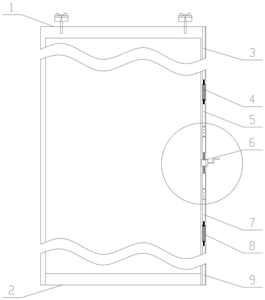
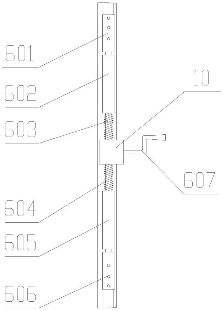
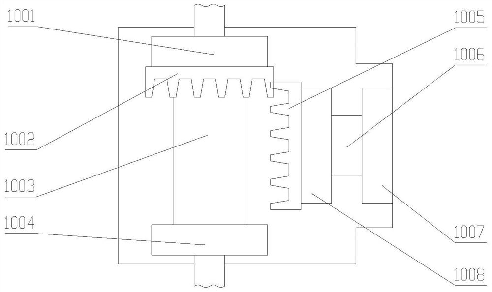
[0024] see Figure 1 to Figure 3 . It should be noted that the structures, proportions, sizes, etc. shown in the drawings attached to this specification are only used to match the content disclosed in the specification, for those who are familiar with this technology to understand and read, and are not used to limit the implementation of the present invention. Limiting conditions, so there is no technical substantive meaning, any modification of structure, change of proportional relationship or adjustment of size, without affecting the effect and purpose of the present invention, should still fall within the scope of the present invention. The disclosed technical content must be within the scope covered. At the sa...


PUM


Abstract

The invention provides a transmission device of a movable partition. The transmission device is characterized in that the transmission device is arranged on one side of a movable partition body, and an upper buffer spring, an upper transmission rod, a threaded transmission mechanism, a lower transmission rod, a lower buffer spring and a lower transmission support rod are sequentially arranged at the bottom of an upper transmission support rod of the transmission device downwards; an upper movable bolt, a forward-rotating threaded rod, a gear box, a reverse-rotating threaded rod, a lower movable bolt and a lower connecting piece are sequentially arranged at the bottom of an upper connecting piece of the thread transmission mechanism downwards; a bearing A, a bevel gear A, a connecting shaftand a bearing B are sequentially arranged on the left side of the interior of the gear box from top to bottom, and the forward-rotating threaded rod and the reverse-rotating threaded rod are screwedto the connecting shaft on the side close to the forward-rotating threaded rod and the reverse-rotating threaded rod correspondingly; and a bevel gear B, a bearing D, a shaft sleeve and a bearing C are sequentially arranged on the right side in the gear box from left to right. By means of the transmission device, the telescopic effect is achieved through forward and reverse rotation of the bevel gear, the space of the movable partition body is saved, and the sound insulation effect of the movable partition body is improved.

Description

technical field [0001] The invention belongs to the technical field of building products, in particular to a transmission device for a movable partition and an adjustment method thereof. Background technique [0002] With the development of society and the continuous advent of new technologies and materials, the role of partitions in indoor space is no longer limited to space division, shelter and privacy protection, and partitions have become a culture; more and more modern and contemporary indoor spaces are using cut off. Corresponding to the convenient and flexible way of partitioning space, the partition itself also has flexible and diverse forms. Choose according to different spaces, needs, style types and different materials. With the continuous development of partitions, there are two main design development directions: fixed partitions and elastic partitions. The most typical feature of elastic partitions is convenience, convenience and flexibility to move at will....

Claims


Application Information

Patent Timeline
Patent Type & Authority Applications(China)
IPC IPC(8): E04B2/74E04B2/82
CPCE04B2/74E04B2/7403E04B2/821
Inventor 齐永军
Owner 杰玛建筑科技(上海)有限公司
Learn More