Blade, axial flow fan blade and fan

A technology of axial flow blades and blades, which is applied in the field of blades, axial flow blades and fans, can solve the problems of increased motor costs, etc., and achieve the effects of improving aerodynamic performance, increasing outlet wind speed, and improving workability

Pending Publication Date: 2020-11-24
GREE ELECTRIC APPLIANCES INC
View PDF0 Cites 3 Cited by
  • Summary
  • Abstract
  • Description
  • Claims
  • Application Information

AI Technical Summary

Problems solved by technology

In order to reduce the temperature rise of the motor, the cost of the motor will increase accordingly

Method used


Image

  • Blade, axial flow fan blade and fan
  • Blade, axial flow fan blade and fan
  • Blade, axial flow fan blade and fan

Examples


Embodiment 1

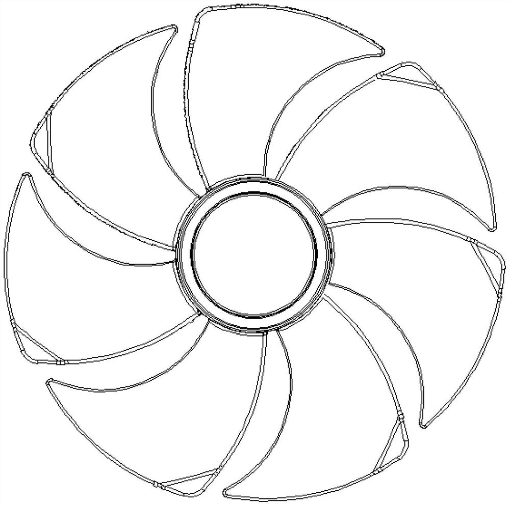
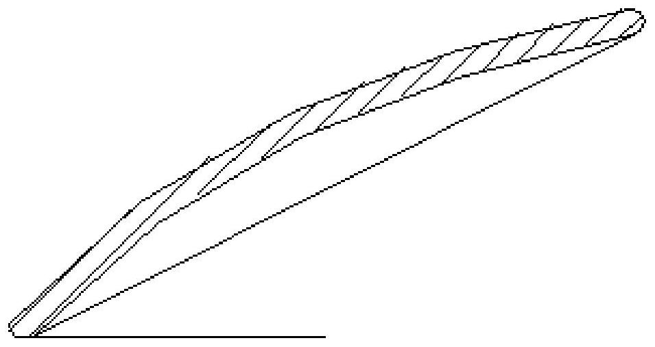
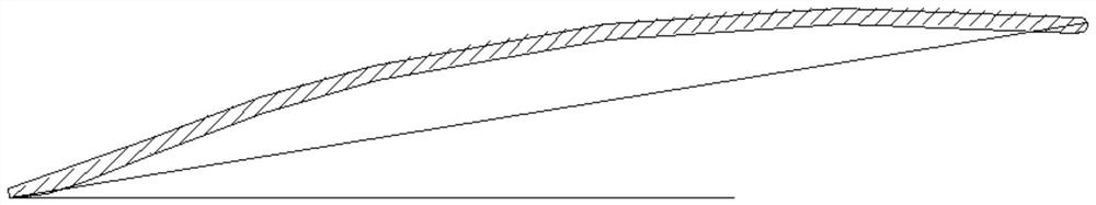
[0053] This embodiment provides a blade, which can be applied to axial flow blades. In one embodiment, such as Figure 4 to Figure 11 As shown, the blade 2 includes a pressure surface, a suction surface 26, a blade root portion 23, a blade top portion 24, a leading edge portion 21, and a trailing edge portion 22, and the cylindrical surface where the blade root portion 23 is defined is the blade root element surface 31. The cylindrical surface where the leaf top 24 is located is the blade top primitive surface 34, and the cylindrical surface located in the middle of the blade root primitive surface 31 and the blade top primitive surface 34 is the 1 / 2 primitive surface 32, which is located at the blade top The cylindrical surface between the primitive surface 34 and the 1 / 2 primitive surface 32 is the 3 / 4 primitive surface 33 .

[0054] The maximum distance between the leading edge portion 21 and the trailing edge portion 22 at the base element surface 31 of the blade root is l...

Embodiment 2

[0068] This embodiment provides an axial fan blade, including a hub 1 and a plurality of blades as provided in Embodiment 1 uniformly distributed along the circumference of the hub 1 .

[0069] Tests have proved that compared with the common fan blades in the prior art, the axial-flow fan blade provided by this embodiment can significantly increase the wind speed at the center of the fan blade by 1m / s and the air volume by 2m 3 / min. At 1100rpm, the power of the motor is reduced by 2W, and the temperature rise of the motor is reduced, which is beneficial to control the cost. The axial-flow fan blade can be matched with the motor to improve energy efficiency and reduce the cost of the motor. At the same time, it can effectively reduce the humming sound during high-speed rotation and improve the sound quality.

[0070] In one embodiment, the diameter of the hub 1 is d, the outer diameter of the axial flow blade is D, and 0.25≤d / D≤0.3. Can reasonably control air separation and ...

Embodiment 3

[0073] This embodiment provides a fan, including the axial flow blade provided in the above embodiments.


PUM


Abstract

The invention relates to the technical field of fans, and particularly relates to a blade, an axial flow fan blade and a fan. The blade comprises a pressure surface, a suction surface, a blade root part, a blade top part, a front edge part and a rear edge part, wherein a cylindrical surface where the blade root part is located is defined as a blade root element surface, a cylindrical surface wherethe blade top part is located is defined as a blade top element surface, a cylindrical surface located between the blade root element surface and the blade top element surface is a 1/2 element surface, and a cylindrical surface located between the blade top element surface and the 1/2 element surface is a 3/4 element surface; and the maximum distance between the front edge part and the rear edgepart at the blade root element surface is l1, the maximum distance between the front edge part and the rear edge part at the 1/2 element surface is l2, the maximum distance between the front edge partand the rear edge part at the 3/4 element surface is l3, the maximum distance between the front edge part and the rear edge part at the blade top element surface is l4, and the values of 11, 12, 13 and 14 gradually increases. The outlet air speed can be effectively increased, the pneumatic performance of the blade is matched with a motor, and the air volume of the fan made of the blade is guaranteed.

Description

technical field [0001] The invention relates to the technical field of fans, in particular to a blade, an axial flow blade and a fan. Background technique [0002] As the core component of the electric fan, the axial fan blade plays a decisive role in the air volume and noise of the whole machine. Ordinary axial-flow fan blades mostly adopt continuous smooth curved surface shape in the design of the blade shape, such as Figure 1 to Figure 3 As shown in Fig. 1, the profile lines of each section transition smoothly and the curvature is small. This kind of blade design is fast, the airflow direction is forward, and the air outlet is divergent. [0003] When working, the motor drives the fan blades, so that the fan blades rotate at a high speed to drive the airflow to flow forward. In order to make the fan have high energy efficiency, that is, the ratio of the work done by the fan to the power consumed by the motor is the largest, it is very important to reasonably match the ...

Claims


Application Information

Patent Timeline
Patent Type & Authority Applications(China)
IPC IPC(8): F04D29/38F04D29/32F04D29/66
CPCF04D29/386F04D29/388F04D29/325F04D29/329F04D29/667
Inventor 梁浩柳洲陈宇强王勇刘建优张驰
Owner GREE ELECTRIC APPLIANCES INC
Why Eureka
Try Eureka