Decoupling structure between adjacent rectangular patches in dual-band antenna array

A rectangular patch, dual-frequency antenna technology, applied in the field of antenna decoupling, can solve the problems of increasing the size of the patch antenna, destroying the low-profile characteristics of the patch antenna, etc., and achieving a good decoupling effect

Active Publication Date: 2020-11-24
NANJING UNIV OF SCI & TECH
View PDF15 Cites 9 Cited by
  • Summary
  • Abstract
  • Description
  • Claims
  • Application Information

AI Technical Summary

Problems solved by technology

Most of the decoupling methods are for single-frequency patch antenna arrays, but with the improvement of application requirements and technology, dual-frequency antenna arrays have gradually become the development trend and requirements. The literature "Dual-Band Metasurface-Based Decoupling Method for Two Closely Packed Dual-Band Antennas" proposes a method of decoupling dual-band pa...

Method used


Image

  • Decoupling structure between adjacent rectangular patches in dual-band antenna array
  • Decoupling structure between adjacent rectangular patches in dual-band antenna array
  • Decoupling structure between adjacent rectangular patches in dual-band antenna array

Examples


Embodiment Construction

[0014] It should be noted that if there is a directional indication (such as up, down, left, right, front, back...) in the embodiment of the present invention, the directional indication is only used to explain that it is in a specific posture (as shown in the drawings). If the specific posture changes, the relative positional relationship, movement, etc. of the components below will also change the directional indication accordingly.

[0015] In addition, if there are descriptions involving "first", "second", etc. in the embodiments of the present invention, the descriptions of "first", "second", etc. are only used for descriptive purposes, and cannot be understood as instructions or implications Its relative importance or implicitly indicates the number of technical features indicated. Therefore, the features defined with "first" and "second" may explicitly or implicitly include at least one of the features. In addition, the technical solutions between the various embodiments ...


PUM


Abstract

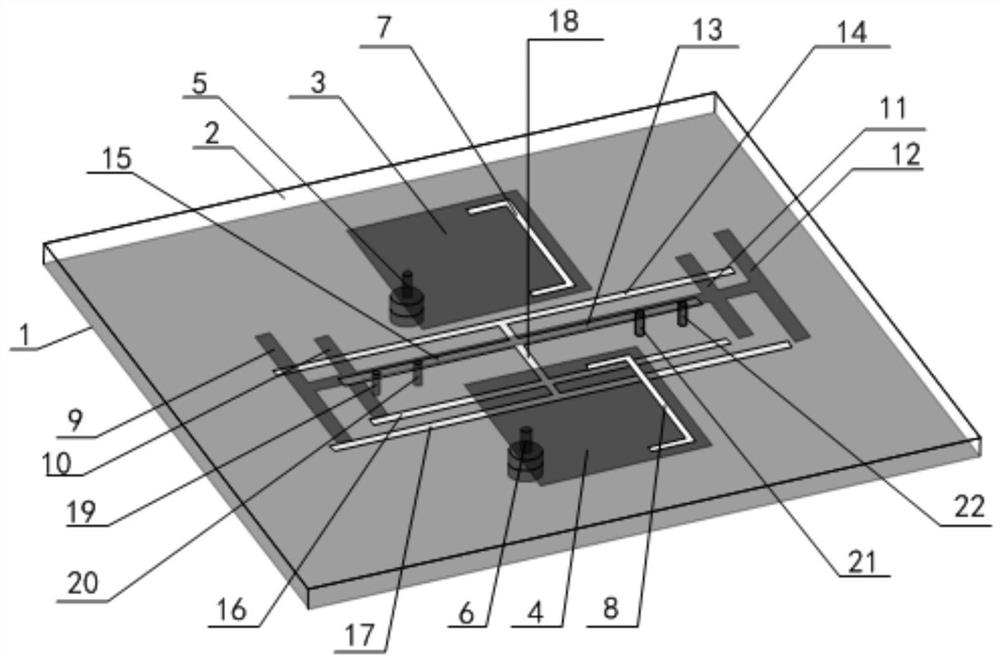
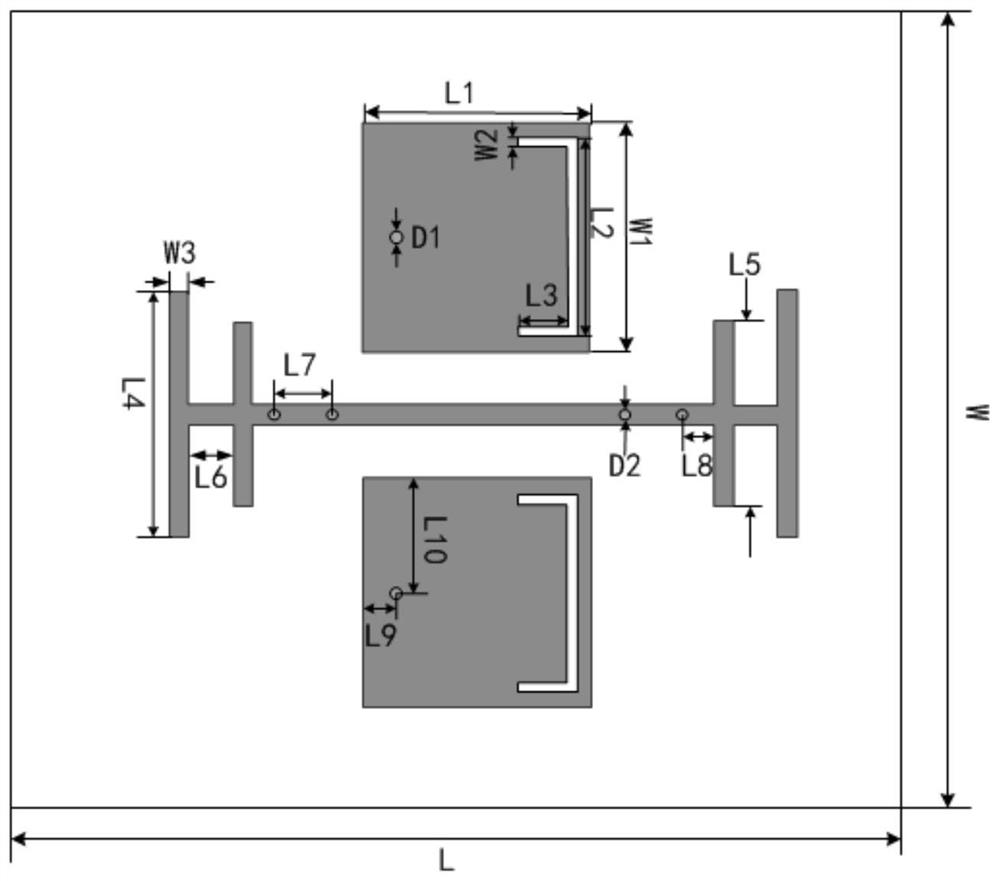
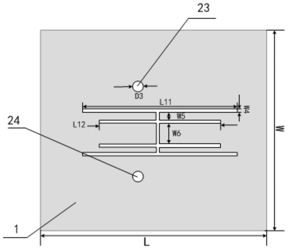
The invention discloses a decoupling structure between adjacent rectangular patches in a double-frequency antenna array. The decoupling structure comprises a dielectric substrate, metal grounding plates arranged on the lower surface and the upper surface of the substrate respectively and two symmetrical double-frequency metal patches. Two feed probes are arranged on the metal grounding plate and penetrate through the dielectric substrate to be in contact with the two patches respectively; a decoupling branch unit and a short-circuit probe unit are arranged between the two patches, decoupling of space waves between the two patches is achieved, and a short-circuit probe is arranged on the metal grounding plate and penetrates through the dielectric substrate to make contact with the decoupling branch unit; U-shaped grooves are symmetrically etched in the two patches and used for activating the other mode; and a defected ground structure is etched on the metal grounding plate and is used for preventing current from flowing from one patch to the other patch. The patch antenna array has the advantages of being low in profile, low in manufacturing cost, simple in structure and the like, the original advantages that the decoupling structure is low in profile, easy to manufacture and the like are kept, the original radiation performance of the antenna is not damaged, and meanwhile a good decoupling effect is obtained.

Description

Technical field [0001] The invention belongs to the technical field of antenna decoupling, and particularly relates to a decoupling structure between adjacent rectangular patches in a dual-frequency antenna array. Background technique [0002] The patch antenna array is one of the most typical antenna forms in the MIMO system due to its low profile, easy integration and diversified performance. Under such a development trend, it is necessary to reduce the mutual coupling between the patch antenna units. Research is endless. [0003] Some typical technologies are: Defective Ground Structure (DGS), Electromagnetic Band Gap Structure (EBG), introduction of neutralization line, decoupling network method, decoupling using resonant structure, etc. Most of the decoupling methods are aimed at single-frequency patch antenna arrays, but with the increase in application requirements and technical improvements, dual-frequency antenna arrays have gradually become the development trend and requ...

Claims


Application Information

Patent Timeline
IPC IPC(8): H01Q1/52H01Q21/00H01Q1/38H01Q1/48H01Q1/50
CPCH01Q1/38H01Q1/48H01Q1/50H01Q1/523H01Q21/00H01Q21/0006
Inventor 朱佳敏邵蔚裴天齐王建朋吴文
Owner NANJING UNIV OF SCI & TECH
Why Eureka
Try Eureka