
Automatic rotor dismounting device of subway traction motor

A traction motor, automatic disassembly technology, applied in the direction of electromechanical devices, electric components, manufacturing motor generators, etc., can solve the problems of affecting efficiency, low efficiency, adding steps, etc., and achieve the effect of simple structure and convenient use

Active Publication Date: 2020-11-24
CHONGQING VOCATIONAL INST OF ENG
View PDF3 Cites 0 Cited by
  • Summary
  • Abstract
  • Description
  • Claims
  • Application Information

AI Technical Summary

Problems solved by technology

[0006] The entire disassembly process requires at least two workers to operate, which is very inefficient
Moreover, after dismantling, the rotating shaft needs to be placed on the transfer vehicle, which increases the steps and affects the efficiency.

Method used


Image

  • Automatic rotor dismounting device of subway traction motor
  • Automatic rotor dismounting device of subway traction motor
  • Automatic rotor dismounting device of subway traction motor

Examples


Embodiment Construction

[0048] The following will clearly and completely describe the technical solutions in the embodiments of the present invention with reference to the drawings in the embodiments of the present invention.

[0049] In describing the present invention, it should be understood that the terms "upper", "lower", "front", "rear", "left", "right", "top", "bottom", "inner", " The orientation or positional relationship indicated by "outside", etc. is based on the orientation or positional relationship shown in the drawings, and is only for the convenience of describing the present invention and simplifying the description, rather than indicating or implying that the referred device or element must have a specific orientation, so as to Specific orientation configurations and operations, therefore, are not to be construed as limitations on the invention.

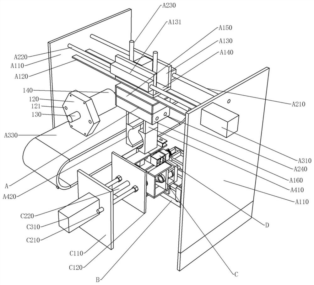
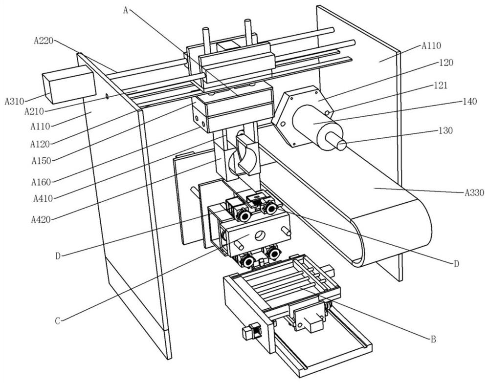
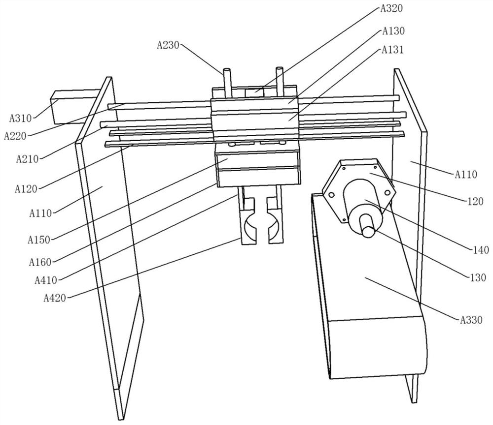
[0050] see Figure 1-Figure 31 , the rotor automatic dismounting device of this embodiment includes:

[0051] The positioning module B ...


PUM


Abstract

The invention discloses an automatic rotor dismounting device of a subway traction motor. The automatic rotor dismounting device can perform full-automatic dismounting on a rotor. The device comprisesa positioning module used for lifting a traction motor and conveying the traction motor to a positioning position; a disassembling module, used for disassembling the end cover from the stator and pulling the rotor out of the stator; and a grabbing module, used for grabbing the disassembled and pulled-out rotor and then placing the rotor on the conveying belt to be output. The device is simple instructure and convenient to use. Automatic positioning, dismounting and rotor outputting of the traction motor can be realized, although the structure is very complex compared with the structure of adevice adopting full-manual participation at present, full automation can be realized, a technical basis is provided for unmanned maintenance in the future, and the device is a great progress of the subsequent unmanned technology.

Description

technical field [0001] The invention relates to the assembly and disassembly technology of a subway traction motor, in particular to a rotor automatic disassembly device of a subway traction motor. Background technique [0002] see Figure 32 , Figure 18 At present, the traction motor used for traction of subway steel wheels mainly includes the following structure: a stator 110, a rotor 140, a motor shaft 130 is installed on the rotor 140, one end of the motor shaft 130 passes through the stator 110 and can be assembled with it in a circular rotation, and the rotor 140 is loaded into the stator 110, the stator 110 drives the rotor 140 to rotate in a circle, the other end of the motor shaft 130 and the end cover 120 can be assembled in a circle, and the end cover 120 is installed on the stator 110 through four bolts 150, and the end cover 120 A process hole 121 is provided. A supporting block 160 is installed at the bottom of the stator 110 . When overhauling the traction...

Claims


Application Information

Patent Timeline
Patent Type & Authority Applications(China)
IPC IPC(8): H02K15/02
CPCH02K15/0006H02K15/02
Inventor 张浩然
Owner CHONGQING VOCATIONAL INST OF ENG
Learn More