Combine and harvester

A combine harvester and harvester technology, which is applied in agricultural machinery and implements, threshing equipment, applications, etc., can solve the problems of complex supporting structure and high cost, and achieve the effect of simple unloading operation.

Inactive Publication Date: 2020-11-24
KUBOTA LTD
View PDF10 Cites 0 Cited by
  • Summary
  • Abstract
  • Description
  • Claims
  • Application Information

AI Technical Summary

Problems solved by technology

[0021] In the above-mentioned conventional structure, the outer surfaces in the left-right direction are smoothly connected in the front-rear direction, and are held in a position wit

Method used


Image

  • Combine and harvester
  • Combine and harvester
  • Combine and harvester

Examples


no. 1 Embodiment approach

[0078] Hereinafter, a first embodiment of the present invention will be described based on the drawings.

[0079] [Basic structure of the combine harvester of the first embodiment]

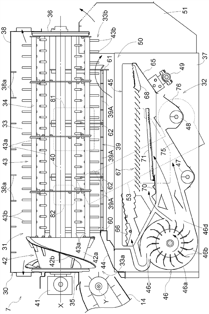
[0080] exist figure 1 , 2 , 3 have shown the whole combine of this embodiment. Right now, figure 1 represents the left view, figure 2 represents the right view, image 3 Represents a plan view, and in these figures, the direction [F] is defined as the front of the traveling body 1, and the direction [B] is defined as the rear of the traveling body 1, image 3 The indicated direction of [L] is defined as the left side of the traveling body 1 , and the direction of [R] is defined as the right side of the traveling body 1 .

[0081] like figure 1 , 2 As shown in , 3 , the combine harvester is provided with a driver's seat 4 on the right front part of the traveling body 1 that can move freely by means of a pair of left and right crawler belt traveling devices 2 . In the cab 3 , a cabin 5 is ...

no. 2 Embodiment approach

[0137] Hereinafter, the case where 2nd Embodiment of this invention is applied to the ordinary type combine which is an example of a combine is demonstrated based on drawing.

[0138] [Overall structure of the second embodiment]

[0139] like Figure 9 , 10 , 11, the common type combine harvester is equipped with a driving unit 103 on the right side of the front part of the traveling body 102 equipped with a pair of crawler belt traveling devices 101, and is equipped with a threshing device 104 for threshing the harvested crops. The grain storage part 105 of the grain storage apparatus which stores the grain obtained by the threshing process. Grain storage unit 105 is equipped with the state that is positioned at the rear side of driving unit 103, and grain storage unit 105 is positioned at the right side of the body and threshing device 104 is positioned at the state of the left side of the body. The valley devices 104 are placed and supported on the body frame 106 so as t...


PUM


Abstract

[Problem] To configure a combine that is capable of simply performing maintenance and inspection of a receiving net of a threshing device from a side close to a storage part in a configuration in which the threshing device and the grain storage part are arranged side by side in the left-right direction. [Solution] The present invention is provided with a threshing device 7 and a grain packing unitwhich are arranged side by side in a machine body, wherein the threshing device 7 is configured to be provided with a threshing barrel 34 that is driven to rotate inside a threshing chamber, a receiving net below the threshing barrel, and a sorting unit below the receiving net. The threshing barrel 34 is configured by integrally forming a raking unit 42 that rakes harvest and sends the harvest rearward and a thresh processing unit 43 that performs thresh processing of the harvest, wherein a maintenance opening W is formed in a side wall of the threshing chamber at a position facing the packing unit on the outside of the threshing processing unit, and a lid body Wa for closing the maintenance opening W is provided in a attachable/detachable manner.

Description

technical field [0001] This invention relates to the combine which was comprised so that a part of the threshing chamber of a threshing apparatus can be opened. [0002] Moreover, this invention relates to the reaper. Specifically, It is related with the reaper provided with the state deviated to one side of a left-right direction. Background technique [0003] [Background Art 1] [0004] As a combine harvester having the above-mentioned structure, it is described in Patent Document 1 that a grain sieve and a grain pan can be alternately moved in and out on the side wall of the threshing device, and an opening for inspection is provided on the side wall with a cover that can be opened and closed freely. Technology. [0005] Moreover, patent document 2 describes the technique which can open the upper part of a threshing chamber largely by installing the top plate of a threshing apparatus openably and closably via a hinge, and opening a top plate. [0006] [Background Techn...

Claims


Application Information

Patent Timeline
IPC IPC(8): A01F12/00A01F12/24A01F12/52
CPCA01F12/24A01F12/00A01F12/52
Inventor 小林宜泰青山祐也川畑舞荒木穰坪井聪美串田吉广
Owner KUBOTA LTD
Why Eureka
Try Eureka