
Autoinjection device having memory element

A technology of automatic injection and memory components, which is applied in the direction of automatic injectors, syringes, hypodermic injection devices, etc., and can solve problems such as difficult and unreliable functions of different functions

Inactive Publication Date: 2020-11-24
NOVO NORDISK AS
View PDF6 Cites 0 Cited by
  • Summary
  • Abstract
  • Description
  • Claims
  • Application Information

AI Technical Summary

Problems solved by technology

[0005] In connection with the design and manufacture of automatic injection devices, variations in tolerances make it difficult or even unreliable to have multiple separate distinct functions operated by the same element
For example, with a syringe as disclosed in WO 2001 / 32255 A1, there is a risk that even if the plunger is triggered the needle shield will not be locked by the locking mechanism
Also, there is a risk that the plunger will not be triggered even if the locking mechanism has been activated

Method used


Image

  • Autoinjection device having memory element
  • Autoinjection device having memory element
  • Autoinjection device having memory element

Examples


Embodiment Construction

[0069] In the context of this disclosure, it may be convenient to define in the figures that the term "distal end" refers to the end of the injection device carrying the injection needle, while the term "proximal" refers to the opposite end of the injection device facing away from the injection needle . The shown figures are schematic diagrams, for which reason the configuration and relative dimensions of the different structures are intended for illustrative purposes only.

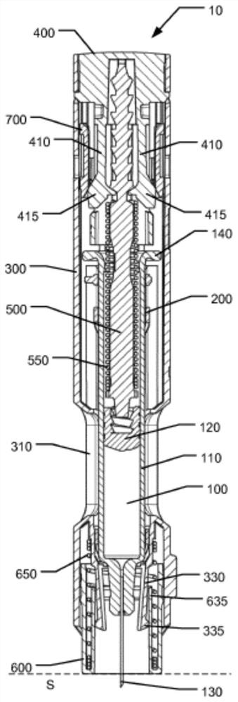
[0070] The following is a description of an exemplary embodiment of a medical injection device 10 for administering a predetermined amount of a liquid medicament. Device 10 is a disposable auto-injector configured to expel a dose of drug in a single administration, after which device 10 is ready for disposal. Figures 1a to 5c Various states of the injection device 10 during its operation are shown in different views, providing a detailed assessment of the principles of operation.

[0071] refer to Fig...


PUM


Abstract

An autoinjection device (10) for expelling a dose of drug from a held drug container (100) is described. A plunger (500) is drivable by an energy source (550) for expelling a dose, the plunger (500) comprising a retaining geometry (515) in retaining engagement with a retaining element (410, 415), wherein the autoinjection device (10) defines a trigger element (700) serving as a memory element movable from a pre-firing position to a fired position, the memory element comprising an engagement surface (700c) configured for sliding engagement with an activation surface (415c) of the retaining element (410, 415), wherein at least one of the engagement surface (700c) and the activation surface (415c) includes a surface being inclined relative to said radial direction, and wherein the energy source (550) acts on the plunger (500) to force the retaining element (410, 415) radially to release the retaining engagement, the radial movement of the retaining element (410, 415) in turn forcing the memory element to move into the fired position.

Description

technical field [0001] The present invention relates to injection devices for injecting medicaments. In particular, the invention relates to an automatic injection device having a releasable plunger, and a memory element controlling an auxiliary function of the automatic injection device, wherein said auxiliary function is different from the function associated with the release of the plunger. Background technique [0002] With some diseases, the patient must infuse the medicament periodically, for example once a week, once a day or even multiple times a day. To help patients overcome their fear of needles, some injection devices contain needle guards, or needle shields, that cover the injection needle before or after administering a drug. Such needle guards or shields generally hide the injection needle from the user's view and, in some forms, additionally provide a mechanical barrier to prevent accidental access to the injection needle by an individual. [0003] US 2017 / ...

Claims


Application Information

Patent Timeline
Patent Type & Authority Applications(China)
IPC IPC(8): A61M5/00A61M5/20A61M5/32
CPCA61M5/00A61M5/2033A61M5/3202A61M2005/2026
Inventor H·赫明森E·基勒里奇
Owner NOVO NORDISK AS
Learn More