Bone wax manufacturing device for orthopedics department

A technology for manufacturing equipment and bone wax, which is applied in the field of orthopedic bone wax manufacturing equipment, can solve problems such as uneven stirring, influence on subsequent use, and loss of raw materials, and achieve the effects of avoiding waste of beeswax, improving work efficiency, and avoiding uneven melting

Pending Publication Date: 2020-11-27
王辉
View PDF3 Cites 3 Cited by
  • Summary
  • Abstract
  • Description
  • Claims
  • Application Information

AI Technical Summary

Problems solved by technology

Close the bleeding pathway between bones to control the bleeding of bone injury. Most of the existing bone wax production is to melt the beeswax first and then pour it into Vaseline for stirring. In the process of pouring the beeswax, it is easy to cause the beeswax to spill out, resulting in raw materials. Loss, resulting in uneven ratio, affecting the subsequent use of bone wax, and the temperature of the newly melted beeswax is high, which is easy to cause burns. The current bone wax stirring is mostly manual stirring, which is time-consuming and laborious, and it is easy to cause improper stirring. average, affecting subsequent use, so it is urgent to make a bone wax manufacturing device for orthopedics

Method used


Image

  • Bone wax manufacturing device for orthopedics department
  • Bone wax manufacturing device for orthopedics department
  • Bone wax manufacturing device for orthopedics department

Examples


Embodiment Construction

[0037] A specific embodiment of the present invention will be described in detail below in conjunction with the accompanying drawings, but it should be understood that the protection scope of the present invention is not limited by the specific embodiment.

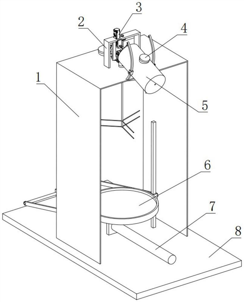
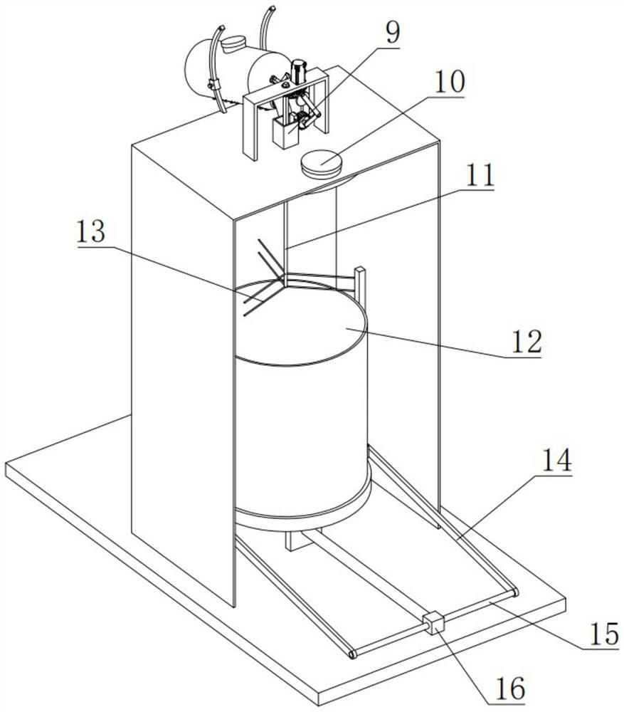
[0038] Such as Figure 1-Figure 17 As shown, the present invention includes a base plate 8, the upper side of the base plate 8 is fixedly connected to the lower side of the U-shaped plate-1 two vertical plates, the upper side of the base plate 8 is fixedly connected to the electric push rod 7, and the upper side of the base plate 8 is fixedly connected symmetrically. The lower end of the guide rod 22, the two guide rods 22 are located in the U-shaped plate-1;

[0039] The upper side of the U-shaped plate-1 horizontal plate is fixedly connected to the lower side of the two vertical plates of the U-shaped plate-2, and the upper end of the U-shaped plate-1 horizontal plate is fixedly connected to the lower end of the symmetri...


PUM


Abstract

The invention discloses a bone wax manufacturing device for the orthopedics department. The device comprises a bottom plate and is characterized in that the upper side of the bottom plate is fixedly connected with the lower sides of two vertical plates of a U-shaped plate I; the upper side of the bottom plate is fixedly connected with an electric push rod; the upper side of the bottom plate is fixedly connected with the lower ends of symmetrical guide rods; the two guide rods are positioned in the U-shaped plate I; the upper side of a transverse plate of the U-shaped plate I is fixedly connected with the lower sides of two vertical plates of a U-shaped plate II; one end of the upper side of the transverse plate of the U-shaped plate I is fixedly connected with the lower ends of symmetricalarc-shaped rods; and the lower side of the U-shaped plate I is fixedly connected with the upper end of an annular ring. The invention relates to the field of bone wax manufacturing, specifically to abone wax manufacturing device for the orthopedics department. According to the device, after beeswax in a raw material barrel is heated and melted through a snake-shaped electric heating wire, the melted beeswax is directly injected into a stirring barrel containing Vaseline by adjusting the angle of the raw material barrel, and beeswax waste caused when the beeswax is transferred is avoided.

Description

technical field [0001] The invention relates to the field of bone wax production, in particular to a bone wax production device for orthopedics. Background technique [0002] Bone wax is a mixture of 70% beeswax and 30% petrolatum. The product is white or light yellow and has good softening properties. It is a material that uses physical methods to block capillary bleeding in the bone marrow. It can be used for various emergency patients to stop bleeding when the bone oozes. It is used for hemostasis when the bones are broken due to different ages, different parts, and different reasons, and when the capillaries in the bone marrow ooze blood caused by drilling or fragmentation of the skull. Close the bleeding pathway between bones to control the bleeding of bone injury. Most of the existing bone wax production is to melt the beeswax first and then pour it into Vaseline for stirring. In the process of pouring the beeswax, it is easy to cause the beeswax to spill out, resulti...

Claims


Application Information

Patent Timeline
Patent Type & Authority Applications(China)
IPC IPC(8): B01F3/20B01F15/02B01F11/00B01F15/06B01F15/00B01F23/70
CPCB01F23/711B01F31/40B01F35/123B01F35/712B01F35/71715B01F35/92B01F2035/99
Inventor 王辉刘宏智崔营营
Owner 王辉
Why Eureka
Try Eureka