
Adjustable workpiece grinding machine

A workpiece and mechanical technology, which is applied in the field of adjustable workpiece grinding machinery, can solve the problems of inconvenient processing of the inner wall of the bell mouth, etc., and achieve the effects of improving grinding efficiency, reducing vibration and improving versatility

Active Publication Date: 2020-11-27
刘微
View PDF13 Cites 7 Cited by
  • Summary
  • Abstract
  • Description
  • Claims
  • Application Information

AI Technical Summary

Problems solved by technology

[0003] General factories mainly use manual operation machinery for workpiece grinding, but the common grinding machines on the market are inconvenient for processing the inner wall of the bell mouth of many workpieces with bell mouth-shaped openings

Method used


Image

  • Adjustable workpiece grinding machine
  • Adjustable workpiece grinding machine
  • Adjustable workpiece grinding machine

Examples


Embodiment 1

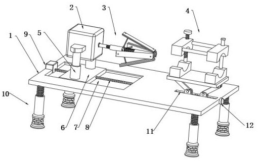
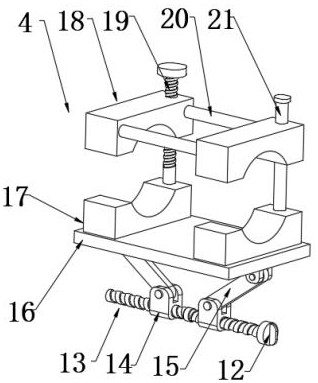
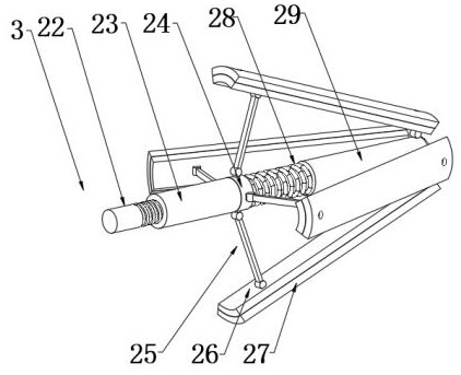
[0026] see Figure 1-5 , an adjustable workpiece grinding machine, including a working panel 1, a grinding motor 2, a grinding head mechanism 3 and a fixing mechanism 4, the working panel 1 is provided with a chute 7, and the chute 7 is provided with an adapted Mounting plate 6, the mounting plate 6 is slidingly connected with the chute 7 and the grinding motor 2 is installed on the mounting plate 6, the grinding motor 2 can be driven to move along the chute 7 through the mounting plate 6, and the grinding head mechanism 3 includes a first connecting rod 22 and the second connecting rod 29 connected to one end of the first connecting rod 22, the first connecting rod 22 is provided with a spring 28, the spring 28 is sleeved on the first connecting rod 22 and one end of the spring 28 is connected to the second connecting rod 29 connection, the other end is connected with one end of the movable block 24 arranged on the first connecting rod 22, and the movable block 24 is slidably...

Embodiment 2

[0033] In order to reduce the vibration of the adjustable workpiece during work, this embodiment is further improved on the basis of Embodiment 1. The improvement is: a backing plate 32 is provided under the pad leg 10, and the backing plate 32 A shock-absorbing mechanism 31 is arranged between the pad leg 10, and the shock generated by the adjustable workpiece during work can be effectively weakened by the shock-absorbing mechanism 31.

[0034] Described damping mechanism 31 comprises damping spring and damping cylinder, and damping spring is sleeved outside the damping cylinder, and one end of damping spring and damping cylinder is connected with pad leg 10, and the other end is connected with backing plate 32, through damping Shock springs and shock-absorbing cylinders can reduce the vibration of adjustable workpieces during work.


PUM


Abstract

The invention discloses an adjustable workpiece grinding machine. The adjustable workpiece grinding machine comprises a working panel, a grinding motor, a grinding head mechanism and a fixing mechanism, wherein a sliding chute is formed in the working panel; a matched mounting plate is arranged in the sliding chute; the mounting plate is in slip connection with the sliding chute, and the grindingmotor is arranged on the mounting plate; and the grinding head mechanism comprises a first connecting rod and a second connecting rod connected with one end of the first connecting rod. When the adjustable workpiece grinding machine is in use, working personnel can adjust the heights of the grinding head mechanism, lower fixing blocks and upper fixing blocks according to the size of the horn mouthof a workpiece, the workpiece is clamped and fixed through the lower fixing blocks and the upper fixing blocks, a movable block is pushed to move by rotating an adjustment block to adjust the angle of a nail file, so that the nail file can grind the flared openings of different sizes, and the grinding efficiency of the adjustable workpiece grinding machine is improved.

Description

technical field [0001] The invention relates to a grinding machine, in particular to an adjustable workpiece grinding machine. Background technique [0002] Grinding is a kind of surface modification technology. It generally refers to a processing method that uses rough objects (sandpaper containing higher hardness particles, etc.) to change the physical properties of the material surface through friction. The purpose of its work is to remove the burrs on the surface of the product workpiece , Make it smooth, easy to continue processing or reach the finished product. [0003] General factories mainly use manual operation machinery to grind workpieces, but the common grinding machines on the market are relatively inconvenient for processing the inner wall of the bell mouth of many workpieces with bell mouth-shaped openings. Contents of the invention [0004] The object of the present invention is to provide an adjustable workpiece grinding machine to solve the problems rai...

Claims


Application Information

Patent Timeline
IPC IPC(8): B24B9/00B24B27/02B24B41/00B24B41/06B24B41/04B24B5/36B24B41/02B24B47/06
CPCB24B5/36B24B9/00B24B27/02B24B41/007B24B41/02B24B41/04B24B41/06B24B47/06
Inventor 刘微
Owner 刘微
Learn More