Turnover device for hub casting detection

A technology for turning over devices and castings, applied in workpiece clamping devices, manufacturing tools, etc., can solve the problems of low safety of manual operation, easy to slip, and difficult to disassemble and assemble when turning over and clamping, so as to achieve flexible turning and improve safety. , the effect of saving adjustment time

Inactive Publication Date: 2020-11-27
刁占柱
View PDF7 Cites 3 Cited by
  • Summary
  • Abstract
  • Description
  • Claims
  • Application Information

AI Technical Summary

Problems solved by technology

[0005] The object of the present invention is to provide an overturning device for wheel hub casting inspection, aiming at solving the problem that the overturning, clamping and fixing of wheel hub castings in the prior art is difficult to disassemble and assemble, and it is easy to slip during the overturning process, and at the same time, the safety of manual operation is low. question

Method used


Image

  • Turnover device for hub casting detection
  • Turnover device for hub casting detection
  • Turnover device for hub casting detection

Examples


Embodiment 1

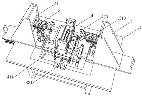
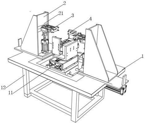
[0026] Such as figure 1 As shown, a turning device for wheel hub casting detection includes a fixed seat 1, the four corners of the bottom of the fixed seat 1 are uniformly formed with supporting legs 12, and the two sides of the top of the fixed seat 1 are fixedly installed with supporting seats 2, two supporting seats The inner side of 2 is provided with a first chute 21, the inside of the first chute 21 is slidably connected with an engaging mechanism 3, the top of the fixed seat 1 is provided with a slot 11, and the inside of the slot 11 is equipped with a turning mechanism 4. During the overturning process of the processed hub, first adjust the engaging mechanism 3 to a suitable level through the two first slide grooves 21 inside the support seat 2, and then support and fix the hub, which needs to be supported and overturned by the overturning mechanism 4 , The support seat 2 is composed of a bottom plate and two side plates symmetrically integrally formed on the top of t...

Embodiment 2

[0028] Such as Figure 2-4 As shown: the two engaging mechanisms 3 include a first slider 31 slidingly connected to the inside of the first chute 21, and one side of the two first sliders 31 is fixedly connected with a mounting block 311, and the top of the mounting block 311 is opened There is a second chute 312, the inside of the second chute 312 is slidably connected with a second slider 32, one end of the second slider 32 is fixedly mounted with a snap-in plate 313, and the four corners of the snap-in board 313 are fixedly mounted with clips. Combined column 314, one side of the middle part of the engaging plate 313 is fixedly equipped with an electric telescopic rod 33, the two sides of one end of the mounting block 311 are provided with a first groove, and the inside of the first groove is equipped with an electric telescopic rod 33, and an L-shaped base 44 One side of the top is fixedly equipped with a telescopic seat 441, and the two sides of the telescopic seat 441 ar...

Embodiment 3

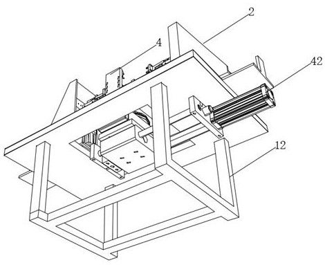
[0031] Such as Figure 5As shown: the turning mechanism 4 includes a first connecting plate 41 and a second connecting plate 412 fixedly connected with the bottom end of the fixed base 1, two guide rods 411 are fixedly installed on both sides of the first connecting plate 41, and the two guide rods 411 A second connecting plate 412 is fixedly installed at one end of the second connecting plate 412, and a second electrohydraulic rod 42 is fixedly installed on one side of the second connecting plate 412. The telescopic end of the second electrohydraulic rod 42 runs through the wall of the first connecting plate 41, and the second The shrinking end of the electro-hydraulic rod 42 is fixedly connected with a sliding seat 421, the inside of the sliding seat 421 is slidably connected with the rod columns of the two guide rods 411, the top of the sliding seat 421 is fixedly connected with an electric turntable 43, and the top of the electric turntable 43 is fixed. The L-shaped base 4...


PUM


Abstract

The invention provides a turnover device for hub casting detection. The turnover device comprises a fixing base, supporting bases are fixedly installed on the two sides of the top of the fixing base,first sliding grooves are formed in the inner sides of the two supporting bases, clamping mechanisms are slidably connected to the interiors of the first sliding grooves, an open groove is formed in the top of the fixing base, and a turnover mechanism is installed in the open groove. The two clamping mechanisms comprise first sliding blocks slidably connected with the interiors of the first sliding grooves. In the turnover device, through cooperation of mounting blocks and electric telescopic rods, clamping plates get close to each other to drive clamping columns to clamp and fix a hub castingand prevent the hub casting from falling off in the turnover process; first electric hydraulic rods ascend and descend to cooperate with the first sliding blocks to adjust the horizontal clamping height of the hub casting between the clamping plates, the time for adjusting manual carrying is saved, the personal safety is guaranteed, and the working efficiency is improved; and meanwhile, when theturnover mechanism turns over the hub casting, clamping adjustment of the hub casting is facilitated.

Description

technical field [0001] The invention belongs to the technical field of hub casting turning over, and in particular relates to a turning device for testing wheel hub castings. Background technique [0002] The wheel hub is a barrel-shaped metal part whose center is mounted on the shaft and is supported by the inner profile of the tire. It is also called rim, steel ring, wheel, tire bell. The wheel hub turning machine reduces the labor intensity of workers to a certain extent and improves work efficiency, but there are still the following disadvantages in the specific use process: [0003] 1) The existing wheel hub turning is fixed by the sleeve ring, the structure is simple, the flexibility after tightening is poor, it cannot be turned flexibly, and the combination and disassembly are inconvenient. The structure of the existing lifting table turning machine is relatively complicated, especially It is the part of the lifting workbench, which not only needs to meet the beat re...

Claims


Application Information

Patent Timeline
Patent Type & Authority Applications(China)
IPC IPC(8): B25B11/00
CPCB25B11/00
Inventor 刁占柱陈芳
Owner 刁占柱
Why Eureka
Try Eureka