Eureka AIR delivers breakthrough ideas for toughest innovation challenges, trusted by R&D personnel around the world.

Automatic vibrating diaphragm punching equipment

An automatic punching and equipment technology, applied in metal processing, sending objects, thin material processing, etc., can solve the problems of affecting the sound quality of speakers, affecting the yield rate, and low work efficiency, so as to ensure accuracy, ensure good product rate, and improve work efficiency effect

Pending Publication Date: 2020-11-27
丰顺县尚平电子有限公司
View PDF0 Cites 0 Cited by
  • Summary
  • Abstract
  • Description
  • Claims
  • Application Information

AI Technical Summary

Problems solved by technology

This method of operation not only has very low work efficiency and high labor intensity, but also if the alignment is not good during punching, it is easy to cause the diaphragm to be scrapped and affect the yield
However, if there is a slight alignment error that is not found, the punched diaphragm cannot be distinguished by the human eye. When installed on the speaker, it will affect the sound quality of the speaker when it is played, and then affect the quality of the product. Sales

Method used


Image

  • Automatic vibrating diaphragm punching equipment
  • Automatic vibrating diaphragm punching equipment
  • Automatic vibrating diaphragm punching equipment

Examples


Embodiment Construction

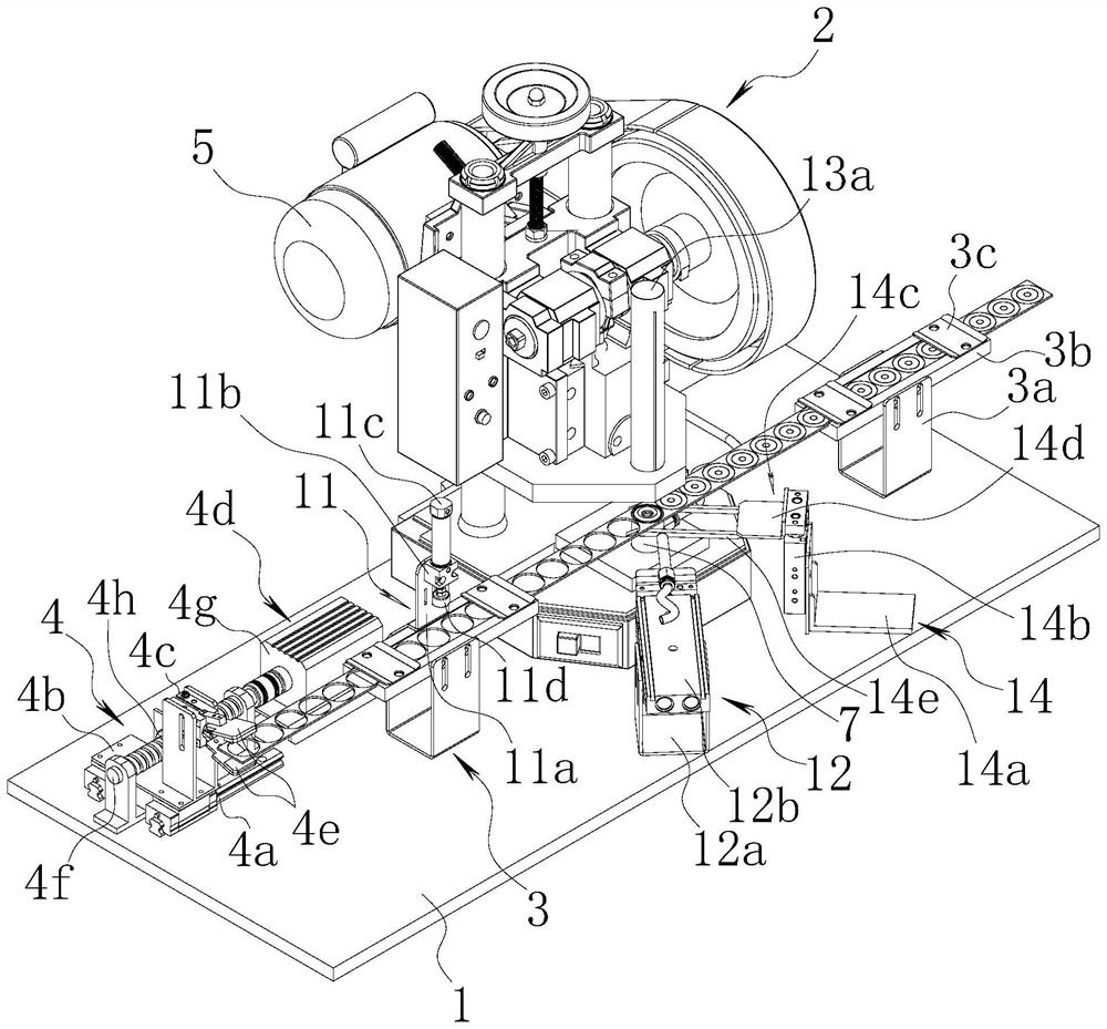
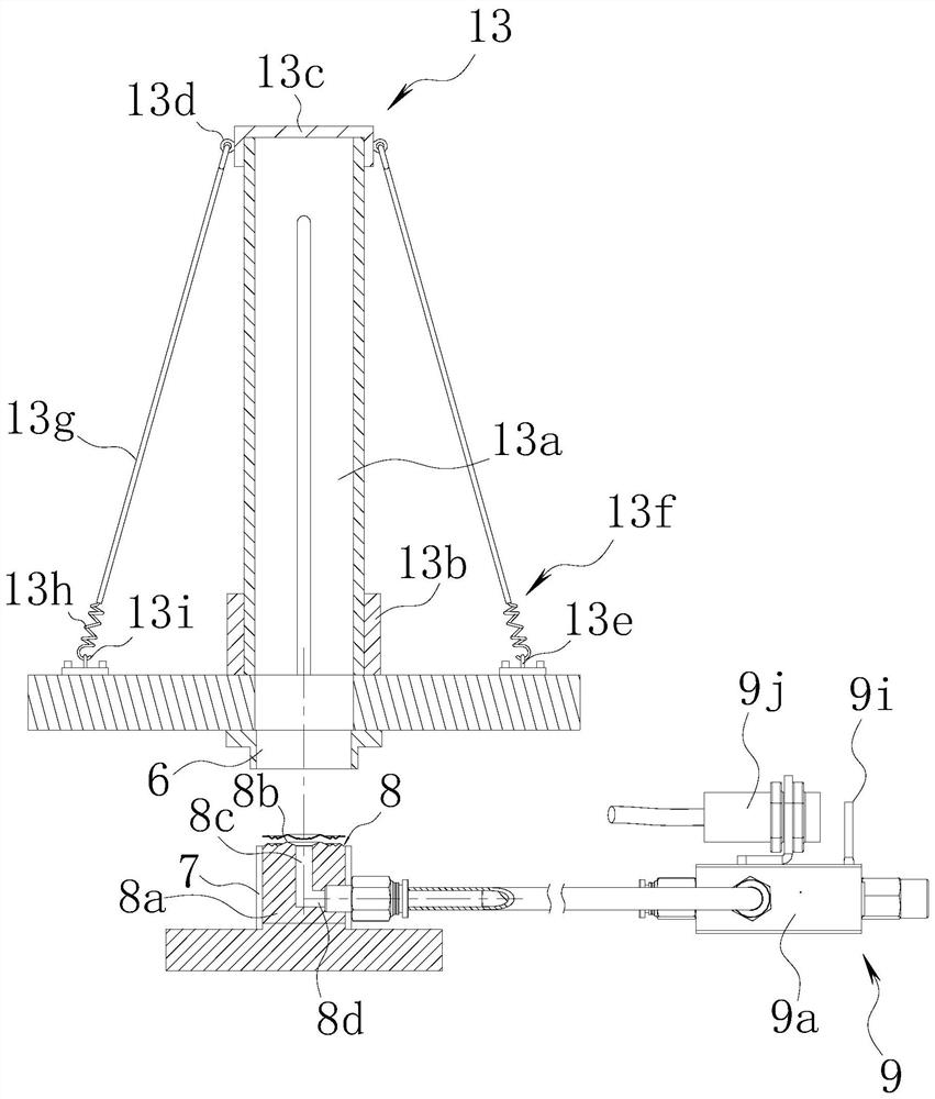
[0031]refer to Figure 1 to Figure 5 As shown, a kind of vibrating film automatic punching equipment of the present invention comprises workbench 1, and described workbench 1 is provided with automatic punching device 2, is provided with to be punched vibrating film on the side of automatic punching device 2 The guide mechanism 3 that is suitable for the strip; the automatic traction mechanism 4 that pulls the moving diaphragm strip to be punched is provided on the workbench 1; the automatic punching device 2 includes a punch 5, and the punch 5 is provided with a punching and The upper mold 6 and the lower mold 7 of the diaphragm are provided with an auxiliary locator 8 inside the lower mold 7, and the upper end surface of the auxiliary locator 8 is adapted to the diaphragm on the diaphragm strip to be punched. The auxiliary locator and the lower die can be of an integrated structure or a separate structure, depending on the specific circumstances.

[0032] The auxiliary posi...


PUM


Abstract

The invention discloses automatic vibrating diaphragm punching equipment and belongs to the technical field of vibrating diaphragm punching equipment. The technical key point is as follows: the automatic vibrating diaphragm punching equipment comprises a worktable, wherein an automatic punching device is arranged on the worktable, and a guiding mechanism matched with a to-be-punched diaphragm strip is arranged on the side edge of the automatic punching device; an automatic traction mechanism which pulls the to-be-punched diaphragm strip to move is arranged on the worktable; the automatic punching device comprises a punch, an upper die and a lower die matched with each other are arranged on the punch, an auxiliary positioner is arranged in the lower die, and the upper end surface of the auxiliary positioner is matched with the diaphragm on the to-be-punched diaphragm strip; the auxiliary positioner is in communication connection to a compressed air source through a negative pressure pipe; a pressure detection mechanism is arranged on the negative pressure pipe, and when the pressure detection mechanism detects a negative pressure at the end of the auxiliary positioner, the punch iscontrolled by an external controller to act to execute punching. The invention aims to provide the automatic vibrating diaphragm punching equipment which is compact in structure, good in aligning effect and high in machining efficiency for automatically punching the diaphragm.

Description

technical field [0001] The present invention relates to a vibrating membrane processing equipment, and more specifically, to an automatic vibrating membrane punching equipment. Background technique [0002] In the production of the existing diaphragm, the diaphragm is formed at intervals along the length direction on the elongated film body by hot pressing forming equipment to form a diaphragm strip. Then the diaphragm strips are manually cut into square semi-finished products, each square semi-finished product contains a diaphragm, and then the square semi-finished products are manually placed in the punching machine and manually aligned, then the diaphragm is punched come out. This mode of operation not only has very low work efficiency and high labor intensity, but also if the alignment is not good during punching, it is easy to cause the diaphragm to be scrapped and affect the yield. However, if there is a slight alignment error that is not found, the punched diaphragm...

Claims


Application Information

Patent Timeline
Patent Type & Authority Applications(China)
IPC IPC(8): B26F1/44B26F1/38B26D7/01B65H35/10
CPCB26F1/44B26F1/38B26D7/015B26D7/018B65H35/10
Inventor 冯胜福冯全胜
Owner 丰顺县尚平电子有限公司
Why Eureka
Eureka Blog
Learn More