Drive-by-wire chassis convenient to clean
A wire-controlled and chassis technology, applied in the field of wire-controlled chassis that is easy to clean, can solve problems such as affecting heat dissipation, inconvenient cleaning of wire-controlled chassis, and easy to ignore natural cooling.
- Summary
- Abstract
- Description
- Claims
- Application Information
AI Technical Summary
Problems solved by technology
Method used
Image

Examples
Embodiment Construction
[0023] The specific implementation manners of the present invention will be further described in detail below in conjunction with the accompanying drawings and embodiments. The following examples are used to illustrate the present invention, but are not intended to limit the scope of the present invention.
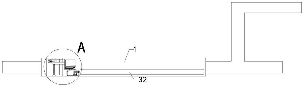
[0024] Such as Figure 1 to Figure 8As shown, a control-by-wire chassis that is easy to clean according to the present invention includes a control-by-wire chassis 1, a rear wheel frame is arranged on the left side of the control-by-wire chassis 1, a front wheel frame and a headstock are arranged on the right side of the control-by-wire chassis 1, and the control-by-wire chassis 1 The middle part of the chassis 1 is provided with a battery placement slot, and also includes a threaded rod 2, a reciprocating screw 3, a limit rod 4 and a fixed rod 5. The front end of the remote control chassis 1 is fixedly connected with a first box 6, and the first box 6 is hollow inside. A...
PUM
 Abstract
Description
Claims
Application Information