
Automated yarn feeding system for twister

A twisting machine and yarn loading technology, which is applied in the field of automatic yarn loading system, can solve the problems of no data interaction between the robot and the twisting machine, manual movement of the creel trolley, lack of overall scheduling and control system, etc., to improve site utilization efficiency, reduce occupancy, and shorten the distance

Pending Publication Date: 2020-11-27
YICHANG JINGWEI TEXTILE MACHINERY
View PDF8 Cites 15 Cited by
  • Summary
  • Abstract
  • Description
  • Claims
  • Application Information

AI Technical Summary

Problems solved by technology

Another patent document CN109355745A discloses a two-for-one twister winding bobbin clamping device and clamping method. The robot removes the twisting winding package and places it on the creel trolley, and the creel trolley needs to be manually moved.
The disadvantage of the existing technology is that there is no data interaction between the robot and the twisting machine, and there is no overall scheduling and control system; the yarn loading must be done after the doffing and the twisting machine stop, and it can only work on the outer side of the creel. Yarn on the working position, intelligent and low degree of automation

Method used


Image

  • Automated yarn feeding system for twister
  • Automated yarn feeding system for twister
  • Automated yarn feeding system for twister

Examples


Embodiment Construction

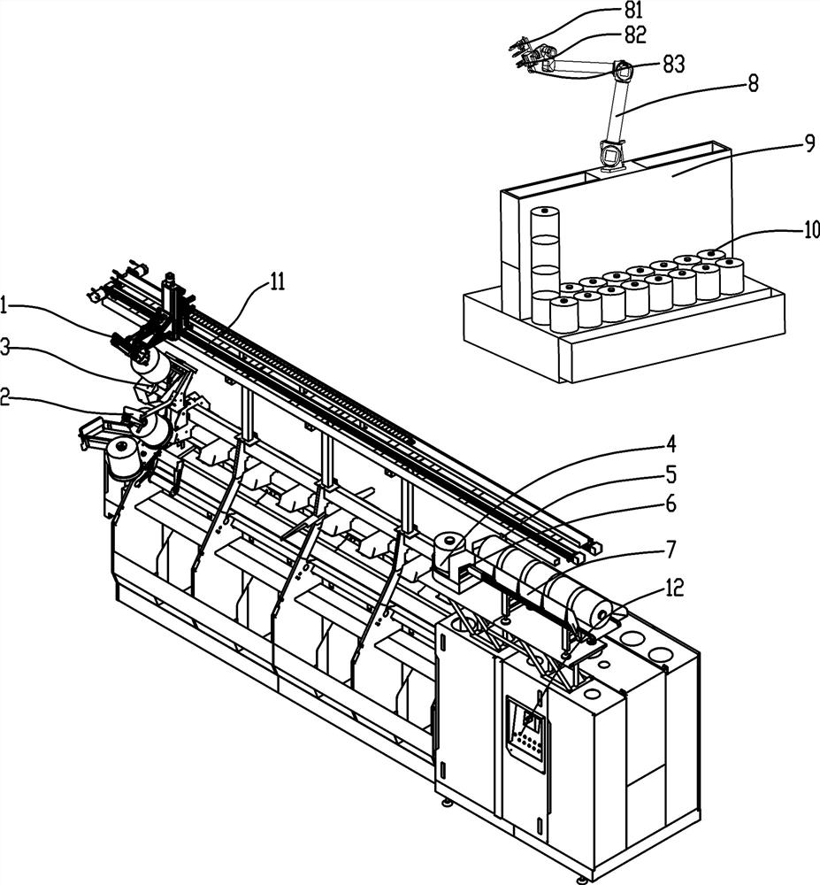
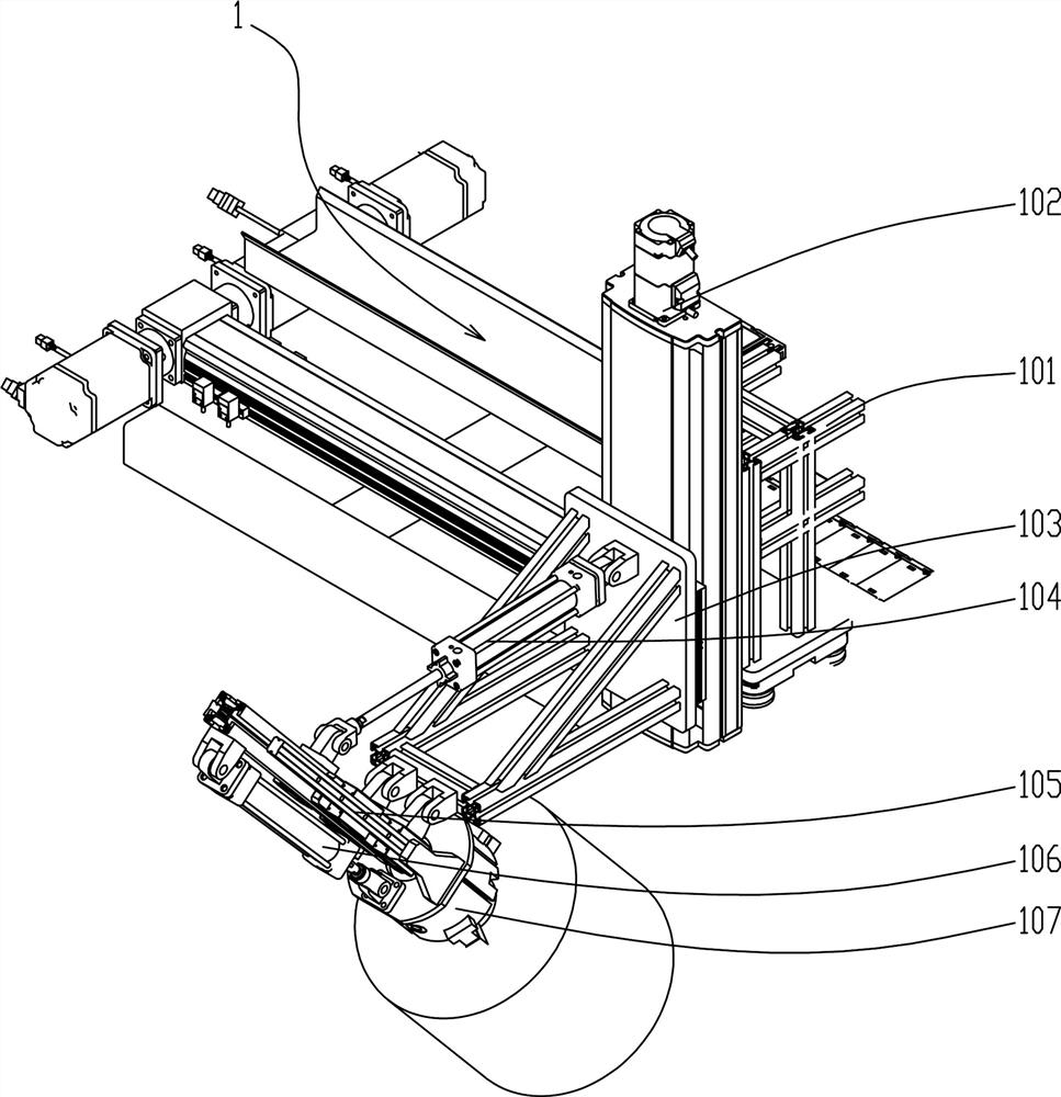
[0040] Such as figure 1 Among them, a kind of automatic yarn loading system for twisting machine, it comprises the upper yarn track 11 that is arranged on the twister 13, and upper yarn track 11 is arranged along the length direction of twister 13, and on yarn upper track 11 There is a yarn loading manipulator 1 that walks along the yarn loading track 11;

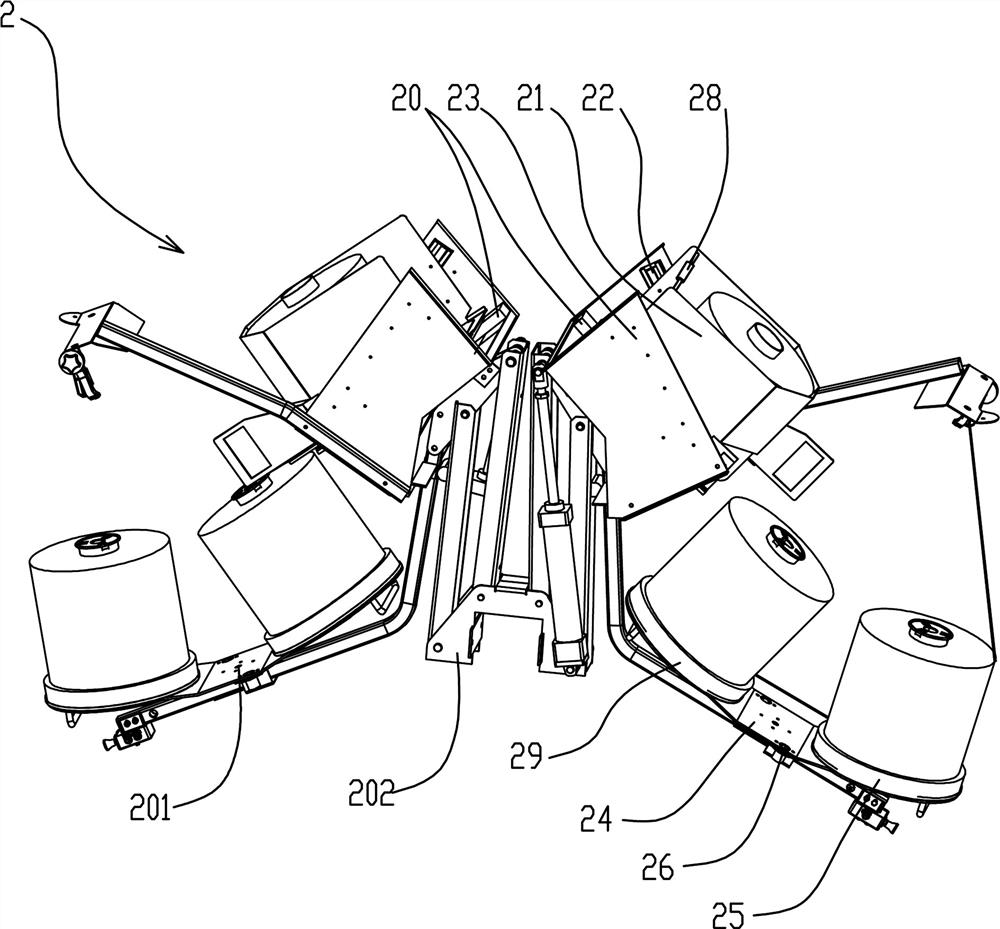
[0041] A supply area 7 is also provided on one side of the upper yarn track 11 for buffering the raw yarn 10, and the upper yarn manipulator 1 is used to transport the raw yarn in the supply area 7 to the upper yarn creel 2 of each spindle position. With this structure, each twisting machine can automatically transport the original yarn 10 to each spindle position, thereby improving the yarn feeding efficiency and reducing the time occupied by the yarn supplying vehicle or other conveying equipment. Improve equipment efficiency across the shop floor.

[0042] The preferred solution is as figure 1 Among them, the upper ya...


PUM


Abstract

The invention provides an automated yarn feeding system for a twister. The automated yarn feeding system comprises a yarn feeding track arranged on the twister. The yarn feeding track is arranged in the length direction of the twister and provided with a yarn feeding mechanical arm, wherein the yarn feeding mechanical arm walks along the yarn feeding track. A supply area is arranged at one side ofthe yarn feeding track and used for temporarily storing grey yarn. The yarn feeding mechanical arm is used for conveying the grey yarn to feeding yarn stands at all spindle stations. The yarn feedingtrack is located in the middle of the top of the twister. The supply area is provided with a structure used for temporarily storing the multiple sets of grey yarn. The supply area is located at the position, at one side of the end of the yarn feeding track, of the top of a control cabinet. The supply area structure is adopted to cooperate with the yarn feeding mechanical arm located on the twister and the rotatable feeding yarn stands, and segmented intelligentized yarn feeding can be achieved; and the yarn fed by a yarn supply vehicle only needs to be conveyed to a buffer area, the grey yarnis conveyed to all the feeding yarn stands through the yarn feeding mechanical arm, and therefore, the automatic yarn feeding efficiency can be improved.

Description

technical field [0001] The invention relates to the field of twisting machines, in particular to an automatic yarn loading system for twisting machines. Background technique [0002] Tire cord, carpet yarn and other twisting equipment adopts two or more strands twisting technology. In order to increase production capacity and save floor space, the outer yarn is usually placed on the creel above the equipment. However, the raw silk packages of cord and carpet yarn are relatively heavy, generally 5-15kg, and the number of stations in a single twisting machine is relatively large, so the yarn loading work brings heavy physical labor to the operator. In addition, in the production of twisted yarn, the production efficiency needs to ensure continuous yarn supply to the twisting machine, so as to avoid the termination of spinning caused by the replacement of the original silk package, which will affect the production efficiency. Therefore, in order to not only reduce the labor in...

Claims


Application Information

Patent Timeline
Patent Type & Authority Applications(China)
IPC IPC(8): D01H9/02
CPCD01H9/02D01H9/00B65H67/02B65H67/065B65H67/067B65H2701/31B25J15/0052B25J5/007B25J9/0093D01H1/18D01H9/18
Inventor 张丕华肖明李永明江海波张明杨华年
Owner YICHANG JINGWEI TEXTILE MACHINERY
Learn More