Paint spraying mechanical equipment

A kind of mechanical equipment, spraying technology, applied in the direction of construction, building structure, etc., can solve the problems of uneven wall coating, low degree of automation, low painting efficiency, etc., to improve painting efficiency, high degree of automation, high adjustment effect of effect

Inactive Publication Date: 2020-11-27
孙支发
View PDF0 Cites 0 Cited by
  • Summary
  • Abstract
  • Description
  • Claims
  • Application Information

AI Technical Summary

Problems solved by technology

[0003] The walls need to be painted during building construction. Most of the existing paint painting methods are manual painting or manual mechanical combination. The degree of automation is low, and the painting efficiency is low. The paint cannot be stirred during painting, resulting in The finished wall paint is uneven, which affects the painting effect

Method used


Image

  • Paint spraying mechanical equipment
  • Paint spraying mechanical equipment
  • Paint spraying mechanical equipment

Examples


Embodiment 1

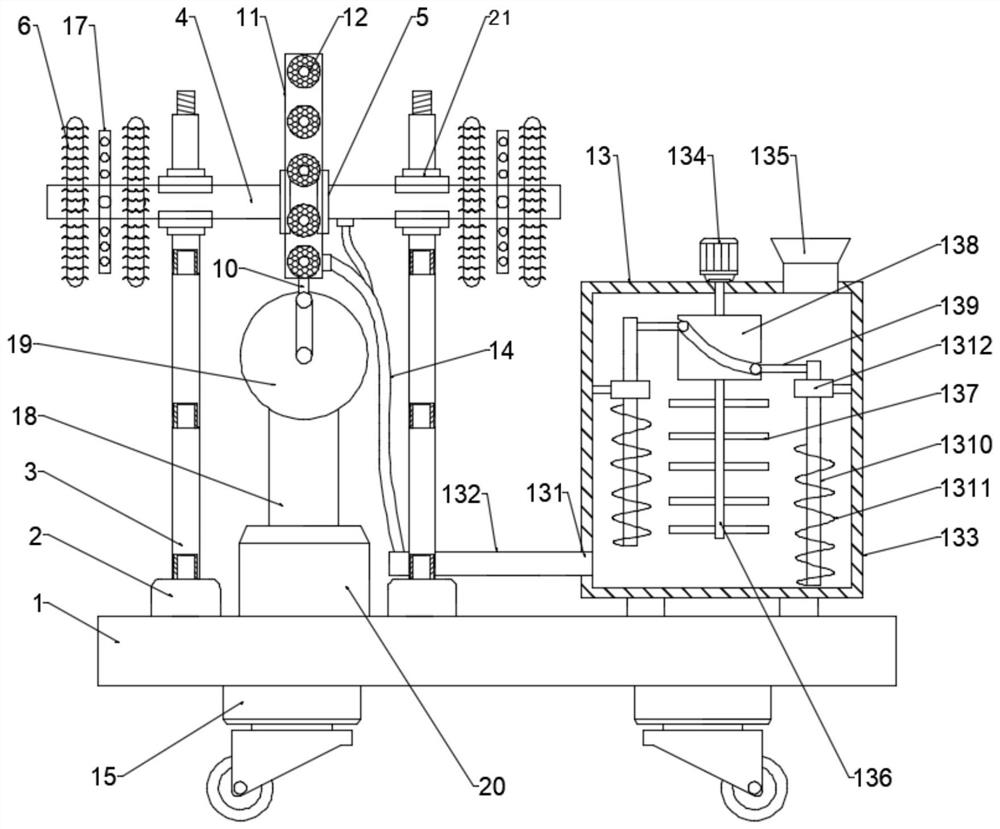
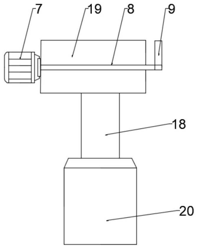
[0025] see figure 1 and 2 , in the embodiment of the present invention, a paint spraying mechanical equipment, including a base 1, two support bases 2 are installed on one side above the base 1, a slide rail 3 is arranged above the support base 2, and the slide rails 3. A first clamping seat 21 is slidably connected, and the first sliding plate 4 is slidably clamped on the first clamping seat 21, so that the first sliding plate 4 can move left and right in the first clamping seat 21. The center of the first sliding plate 4 is provided with a second clamping seat 5, and the left and right sides of the second clamping seat 5 are symmetrically equipped with the first painting device 6, and the middle of the support base 2 is provided with a hydraulic machine base 20, through which 20 The heights of the first painting device 6 and the second painting device 12 can be adjusted according to the height of the construction wall. A hydraulic rod 18 is connected above the hydraulic mac...

Embodiment 2

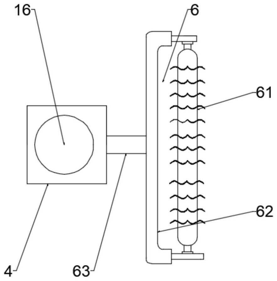
[0030] see image 3 , in this embodiment, the first painting device 6 includes a painting post 61, on which bristles are evenly distributed, and the upper and lower sides of the painting post 61 are hinged with a painting frame 62, and the painting frame 62 passes through a pole 63 is fixedly connected with the first sliding plate 4, and the length of the pole 63 is greater than the height of the first clamping seat 21, so that the first painting device 6 is fixed while avoiding the interference between the painting frame 62 and the first clamping seat 21.

[0031] see Figure 4 , in this embodiment, the second painting device 12 includes a painting plate 121 evenly arranged on the surface of the second sliding plate 11, and a spraying tube 122 is arranged at the center of the painting plate 121, and the spraying tube 122 is connected to the first The spraying device 16 inside the two sliding plates 11 is in communication.

Embodiment 3

[0033] In this embodiment, the stirring device 13 includes a stirring box 133, a rotating motor 134 is arranged on the top of the stirring box 133, a feeding port 135 is arranged on one side of the rotating motor 134, and a connection is made under the rotating motor 134. There is a stirring shaft 136 with a plurality of stirring rods 137 arranged circumferentially.

[0034]In this embodiment, a cylindrical cam 138 is installed on the upper part of the stirring shaft 136, and movable rods 139 are slidably connected to the chute on both sides of the cylindrical cam 138, and the movable rod 139 is fixedly connected to a lifting column 1310, and the lifting column 1310 A spiral stirring blade 1311 is installed below, and the upper part of the lifting column 1310 is slidably connected with a limit sleeve 1312, and the limit sleeve 1312 is fixedly connected with the inner wall of the stirring box 133 through a fixed rod; the stirring shaft 136 drives the cylinder when rotating The ...


PUM


Abstract

The invention relates to the field of building machines, in particular to paint spraying mechanical equipment. The paint spraying mechanical equipment comprises a pedestal. Two supporting bases are installed on one side of the upper portion of the pedestal. Sliding rails are arranged above the supporting bases. A first sliding plate is in clamping connection to the sliding rails in a sliding mode.A clamping connection base is arranged at the center of the first sliding plate. First brushing devices are symmetrically installed on the left side and the right side of the clamping connection base. A second brushing device is arranged on a second sliding plate, and the second sliding plate is in clamping connection with the clamping connection base in a sliding mode. A stirring device is arranged on one side of the supporting bases. A hose communicates with the lower portion of the first sliding plate and the lower portion of the second sliding plate. The paint spraying mechanical equipment is high in degree of automation and easy to operate, the spraying efficiency and spraying effect can be greatly improved and the paint spraying mechanical equipment can be widely applied and popularized.

Description

technical field [0001] The invention relates to the field of construction machinery, in particular to a paint spraying mechanical device. Background technique [0002] Construction engineering refers to the engineering entity formed through the construction of various housing buildings and their ancillary facilities and the installation of supporting roads, pipelines, and equipment. The planning, survey, design and construction, completion and other technical work and the completed engineering entity and the installation project of the supporting lines, pipelines and equipment. [0003] The walls need to be painted during building construction. Most of the existing paint painting methods are manual painting or manual mechanical combination. The degree of automation is low, and the painting efficiency is low. The paint cannot be stirred during painting, resulting in The finished wall paint is uneven, which affects the painting effect. Contents of the invention [0004] Th...

Claims


Application Information

Patent Timeline
Patent Type & Authority Applications(China)
IPC IPC(8): E04F21/12
CPCE04F21/12
Inventor 孙支发
Owner 孙支发
Why Eureka
Try Eureka