
Attached lift scaffold

A lifting scaffolding and attachment technology, which is applied to the accessories of the scaffolding, the scaffolding supported by the house structure, the support of the house structure, etc. General and other problems, to achieve the effect of solving the high construction cost and maintenance cost, improving construction efficiency and reducing labor intensity

Inactive Publication Date: 2020-11-27
深圳市焺腾科技发展有限公司
View PDF5 Cites 0 Cited by
  • Summary
  • Abstract
  • Description
  • Claims
  • Application Information

AI Technical Summary

Problems solved by technology

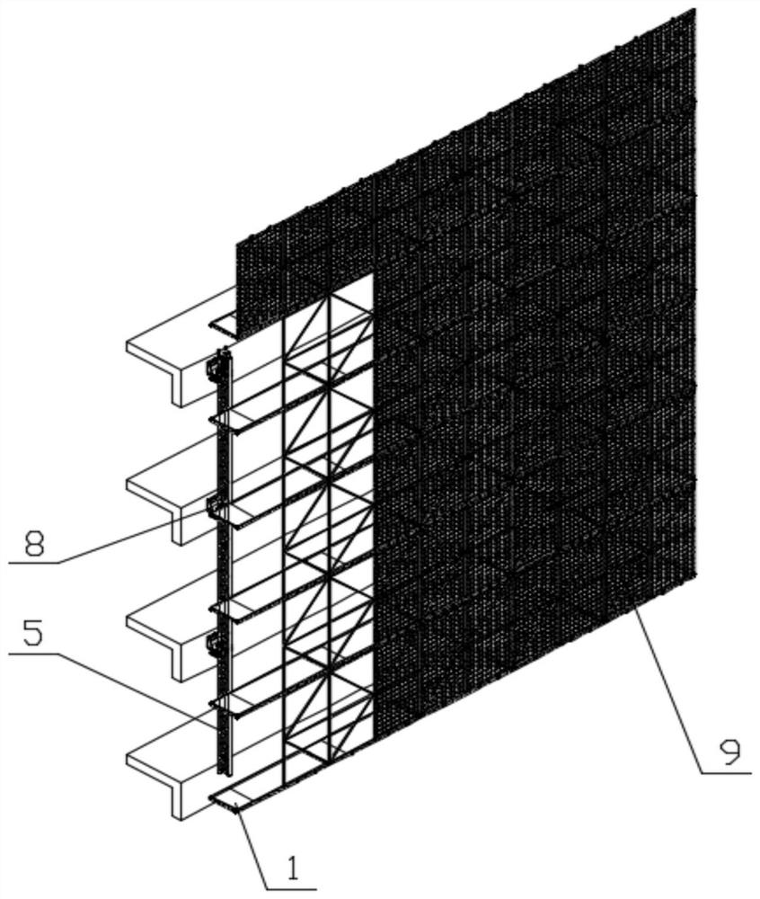
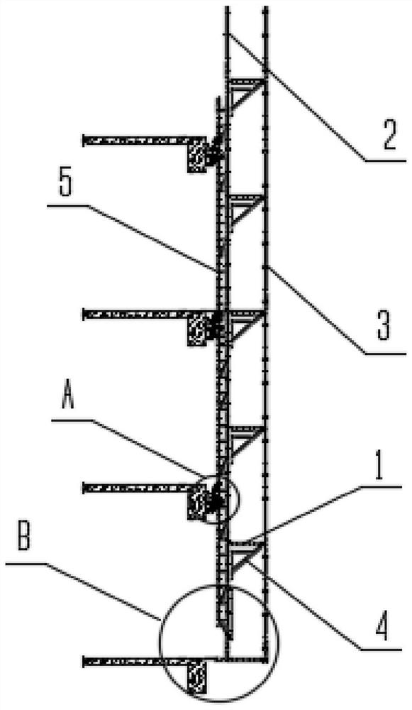
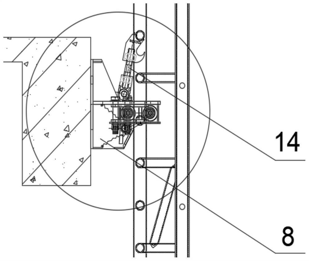
[0004] The purpose of the present invention is to provide an attached lifting scaffold, which is suitable for various high-rise or super-high-rise buildings with simple or complex structural arrangements. It can be assembled on the ground first and then hoisted, or it can be erected layer by layer. Users can freely choose to install The advantages of the method and structure solve the problem that for the attached lifting scaffolds with two different installation methods and structures, because they can only adopt a single fixed installation method and structure, the scope of application is relatively limited and cannot meet the needs of various structural layout buildings. For the use of objects, there are many types of special-shaped structural parts and they are not universal, and some of them need to be reprocessed by on-site installers, which increases the workload of on-site installers and affects the installation progress of attached lifting scaffolding.

Method used


Image

  • Attached lift scaffold
  • Attached lift scaffold
  • Attached lift scaffold

Examples


Embodiment Construction

[0028] In order to make the object, technical solution and advantages of the present invention clearer, the present invention will be further described in detail below in conjunction with the accompanying drawings and embodiments. It should be understood that the specific embodiments described here are only used to explain the present invention, not to limit the present invention.

[0029] The implementation of the present invention will be described in detail below in conjunction with specific embodiments.

[0030] In the drawings of this embodiment, the same or similar symbols correspond to the same or similar components; The indicated orientation or positional relationship is based on the orientation or positional relationship shown in the drawings, and is only for the convenience of describing the present invention and simplifying the description, rather than indicating or implying that the referred device or element must have a specific orientation, or in a specific orien...


PUM


Abstract

The invention relates to the technical field of building construction, and discloses an attached lift scaffold. The attached lift scaffold comprises a shaping profile steel scaffold plate. An outer vertical rod is connected to one side of the shaping profile steel scaffold plate. An inner vertical rod is connected to the other side of the shaping profile steel scaffold plate. A guide rail is fixedto one side of the inner vertical rod. A plurality of connecting mechanisms are connected to the guide rail. One side of the connecting mechanism is fixed to a building main body structure. An auxiliary plate is arranged at the bottom end of the inner vertical rod. One end of the auxiliary plate is connected with the shaping profile steel scaffold plate, and the other end of the auxiliary plate is connected with a turning plate through a pin shaft. The turning plate abuts against a building. The attached lift scaffold is suitable for various high-rise or super high-rise buildings with simpleor complex structures, can be hoisted after being assembled on the ground, and can also be erected layer by layer. A user can freely select the mounting modes and the structures.

Description

technical field [0001] The invention relates to the technical field of building construction, in particular to an attached lifting scaffold. Background technique [0002] At present, in the field of building construction, the traditional fastener-type steel pipe scaffolding is being phased out due to its poor safety assurance, low construction efficiency, and large steel consumption. It is not suitable for high-rise building construction and is not conducive to civilized construction. The attached lifting scaffold used in the existing industry has two installation methods and structures. One is to assemble many small modules in units of standard units on the ground in advance, and then use lifting equipment to hoist. Specifically, it can be divided into two stages. The first stage is the ground assembly of the frame body. Each assembly site is required to be 20m*20m. According to the size of the construction site, an assembly team is set up in each group of 3-4 people. The e...

Claims


Application Information

Patent Timeline
Patent Type & Authority Applications(China)
IPC IPC(8): E04G3/28E04G3/30E04G3/32E04G5/08E04G5/14
CPCE04G3/28E04G3/30E04G3/32E04G5/08E04G5/14E04G2003/286E04G2005/148
Inventor 李永献刘丽陈效宇
Owner 深圳市焺腾科技发展有限公司
Learn More