
Installation method of fresh air handling unit

An installation method and technology for fresh air units, which are applied in heating methods, ventilation systems, space heating and ventilation, etc., can solve the problem of loose mounting holes and bolts, affecting the heat dissipation effect of the fresh air unit, and affecting the installation stability and firmness of the fresh air unit. and other problems to achieve the effect of improving the heat dissipation effect

Active Publication Date: 2020-11-27
ZHEJIANG MEICHEN ENVIRONMENTAL TECH CO LTD
View PDF16 Cites 0 Cited by
  • Summary
  • Abstract
  • Description
  • Claims
  • Application Information

AI Technical Summary

Problems solved by technology

[0005] In order to make up for the deficiencies in the prior art, the present invention proposes an installation method for fresh air units. The present invention is mainly used to solve the problem that most of the existing fresh air units are fixed to the wall by bolts when installing the existing fresh air units. When the fresh air unit is being maintained, bolts need to be removed frequently, which will easily lead to loosening between the mounting holes on the wall and the bolts, which will affect the stability and firmness of the installation of the fresh air unit; at the same time, one side of the fresh air unit is attached To the wall, it will affect the heat dissipation effect of the fresh air unit

Method used


Image

  • Installation method of fresh air handling unit
  • Installation method of fresh air handling unit
  • Installation method of fresh air handling unit

Examples


Embodiment approach

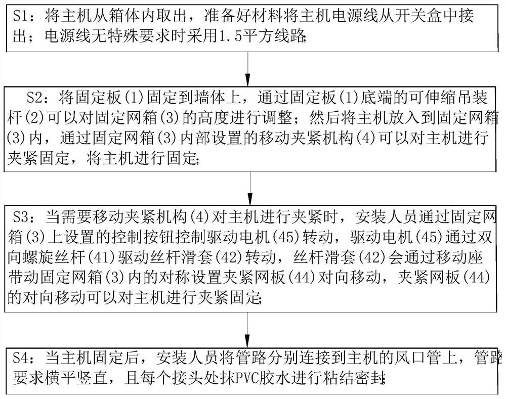
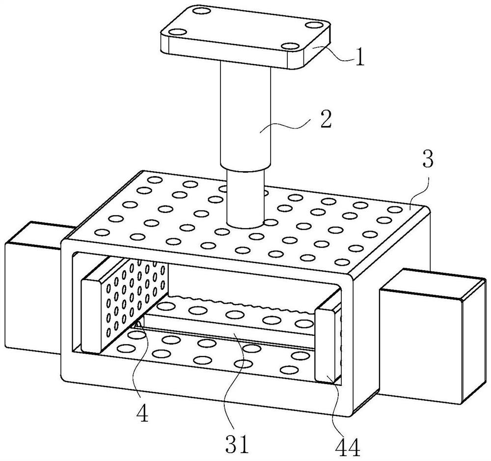
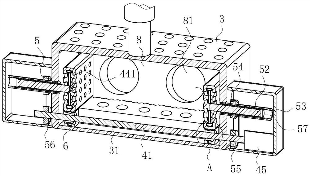
[0034] As an embodiment of the present invention, the mobile clamping mechanism 4 includes a bidirectional screw screw 41, a screw sliding sleeve 42, a sliding seat 43, a clamping net plate 44 and a drive motor 45; the bidirectional screw screw 41 Rotate and insert into the guide chute 31, and the two-way helical screw 41 is symmetrically sleeved with the screw sliding sleeve 42; the top end of the sliding seat 43 is fixed on the clamping net plate 44, and the bottom end of the sliding seat 43 slides Touch the bottom end of the guide chute 31; the sliding seat 43 is provided with a rotating cavity 431, and a screw sliding sleeve 42 is inserted in the rotating cavity 431; the screw sliding sleeve 42 is clamped by the grinding assembly 6 and Sliding seat 43 is connected;

[0035] During work, the direction of rotation of the helix on the bidirectional helical screw 41 is set symmetrically opposite to the two ends along the center of the bidirectional helical screw 41; 45 rotati...


PUM


Abstract

The invention belongs to the technical field of fresh air handling units, and particularly relates to an installation method of a fresh air handling unit. The method comprises the following steps thatS1, a main machine is taken out of a box body, materials are prepared, and a power line of the main machine is led out of a switch box; S2, a fixing plate is fixed to a wall body, then the main machine is placed into a fixed net box, the main machine can be clamped and fixed through a movable clamping mechanism arranged in the fixed net box, and the main machine is fixed; and S3, when the main machine needs to be clamped by the movable clamping mechanism, a driving motor is controlled to rotate through a control button, the driving motor drives a screw rod sliding sleeve to rotate through a bidirectional spiral screw rod, the screw rod sliding sleeve can drive symmetrically-arranged clamping net plates in the fixed net box to move oppositely through a movable seat, and the main machine can be clamped and fixed through the opposite movement of the clamping net plates. According to the method, the main machine can be conveniently clamped and fixed, and the phenomenon that the main machine shakes in the installation net box is prevented.

Description

technical field [0001] The invention belongs to the technical field of fresh air units, in particular to a method for installing fresh air units. Background technique [0002] The fresh air unit is an air-conditioning device that provides fresh air. Functionally, according to the requirements of the use environment, it can achieve constant temperature and humidity or simply provide fresh air. The working principle is to extract fresh air from the outside and send it to the room through the fan after treatment such as dust removal, dehumidification or humidification, cooling or heating, and replace the original indoor air when entering the indoor space. [0003] When installing the existing fresh air unit, most of the fresh air unit is fixed to the wall by bolts, and then the pipeline is connected to the air pipe opening of the fresh air unit. When the fresh air unit needs to be repaired, the bolts need to be removed frequently. In turn, it is easy to cause loosening betwee...

Claims


Application Information

Patent Timeline
IPC IPC(8): F24F7/06F24F13/00F24F13/02F24F13/32
CPCF24F7/06F24F13/00F24F13/0254F24F13/32
Inventor 莫永祺
Owner ZHEJIANG MEICHEN ENVIRONMENTAL TECH CO LTD
Learn More