
Network monitoring terminal with closed space environment monitoring function

An environment monitoring and enclosed space technology, applied in network topology, program control, measuring devices, etc., can solve the problems of not having video image monitoring function, video monitoring terminal not having environment monitoring function, information integration degree is not high, etc., to improve The effect of system response ability, reduction of false alarm probability, and good shooting ability

Pending Publication Date: 2020-11-27
NANJING UNIV OF SCI & TECH
View PDF8 Cites 0 Cited by
  • Summary
  • Abstract
  • Description
  • Claims
  • Application Information

AI Technical Summary

Problems solved by technology

[0004] However, since existing environmental monitoring terminals usually do not have video image monitoring functions, most of the same video monitoring terminals also do not have environmental monitoring functions, resulting in the environmental monitoring and video monitoring technical solutions in closed spaces usually requiring two sets of terminal equipment and two This will bring additional costs to equipment installation, line laying and subsequent maintenance
In addition, since environmental monitoring and video surveillance are both necessary functional requirements for a specific closed environment, meeting the above requirements through two sets of terminal equipment will lead to a low degree of information integration, requiring the host computer system to aggregate and monitor data. deal with

Method used


Image

  • Network monitoring terminal with closed space environment monitoring function
  • Network monitoring terminal with closed space environment monitoring function
  • Network monitoring terminal with closed space environment monitoring function

Examples


Embodiment

[0048] Such as Figure 5(a) ~ Figure 5(d) As shown, the outline structure of the network monitoring terminal of this embodiment includes a USB interface 1, a power indicator light 2, a network cable interface 3, a network indicator light 4, a power switch 5, smoke and combustible gas sensors 6, a temperature and humidity sensor 7, a camera 8, Infrared emitting LED lamp 9, WIFI antenna 10 and cloud platform 11. The USB interface 1 provides USB power supply for the terminal; the power indicator light 2 shows whether the power supply of the current terminal is connected; the network cable interface 3 is used to connect to the Ethernet network; the network indicator light 4 shows whether the current terminal network is connected; The power switch 5 is an integral terminal power switch; the camera 8 is equipped with an infrared emitting LED9 to provide nighttime shooting capability, and is installed on the cloud platform 11; the temperature and humidity sensor 7 can provide a close...


PUM


Abstract

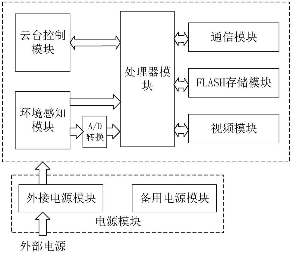
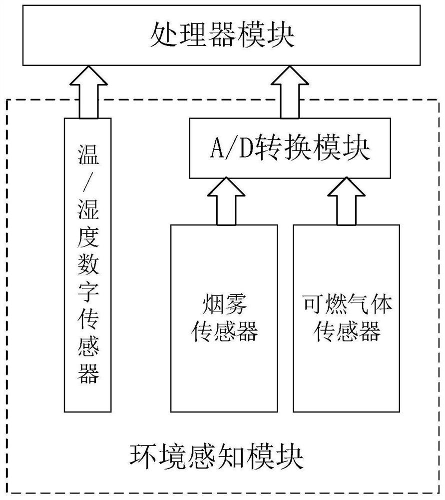
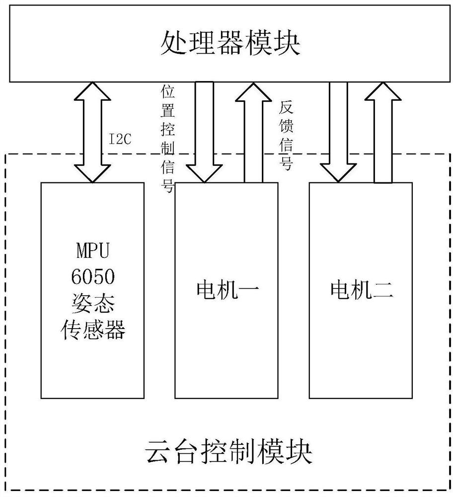
The invention discloses a network monitoring terminal with an enclosed space environment monitoring function. The network monitoring terminal comprises a processor module, a power supply module, a pan-tilt control module, an environment sensing module, an A / D conversion module, a communication module, a FLASH storage module and a video module. The processor module comprises a CPU module and expands a data bus of the CPU module; the power supply module supplies power to the terminal; the pan-tilt control module communicates with the processor module through a control line and a signal line to complete camera attitude control. The environment sensing module collects current environment data and then transmits the data to the processor module through a digital-to-analog conversion module anda single bus. The communication module, the FLASH storage module and the video module are in data transmission with the processor module through a data bus, and the modules are controlled to work through a control bus. The network monitoring terminal is used for being installed in a closed space, and has the functions of closed space temperature and humidity monitoring, smoke monitoring, video image acquisition and the like.

Description

technical field [0001] The invention relates to a network monitoring terminal, in particular to a network monitoring terminal with a closed space environment monitoring function. Background technique [0002] Environmental monitoring and video surveillance in enclosed spaces have always been an important requirement for fire protection and safety systems, and monitoring terminals and environmental monitoring terminals have always been important components of fire safety systems. At present, there are many devices with high energy consumption, high value and high environmental requirements in enclosed spaces such as bank data centers, enterprise server rooms, and ship power cabins. In order to ensure the safe and stable operation of these devices, it is necessary to pass the environment The monitoring device implements remote monitoring and control of the environmental conditions of its internal equipment operation, and needs to take internal pictures through the video monito...

Claims


Application Information

Patent Timeline
IPC IPC(8): G05B19/042G01D21/02H04N5/225H04N7/18H04W84/12
CPCG05B19/042G01D21/02H04N7/18H04W84/12H04N23/00
Inventor 吴沛霆成旭黄炎焱张振
Owner NANJING UNIV OF SCI & TECH
Learn More