Cable cutter

A cable and driving device technology, applied in the field of cable cutters, can solve problems such as time-consuming, labor-intensive safety, internal complexity, and high transportation costs, and achieve the effects of saving operation and construction time, simple overall structure, and improving cutting efficiency

Inactive Publication Date: 2020-11-27
GUANGDONG POWER GRID CO LTD +1
View PDF7 Cites 1 Cited by
  • Summary
  • Abstract
  • Description
  • Claims
  • Application Information

AI Technical Summary

Problems solved by technology

When installing the cable, the cable will be cut according to the needs of the construction site. The commonly used wire cutter needs to place the human hand on the handle of the wire cutter to cut the cable manually, which is time-consuming and laborious and has insufficient safety. The existing cable cutting device The structure is huge and the interior is intricate. When using it, it needs to be deployed in time on site. The use conditions are limited, and it is not easy to carry and use with the car, which reduces the work efficiency and costs a lot of transportation costs.

Method used


Image

  • Cable cutter
  • Cable cutter
  • Cable cutter

Examples


Embodiment 1

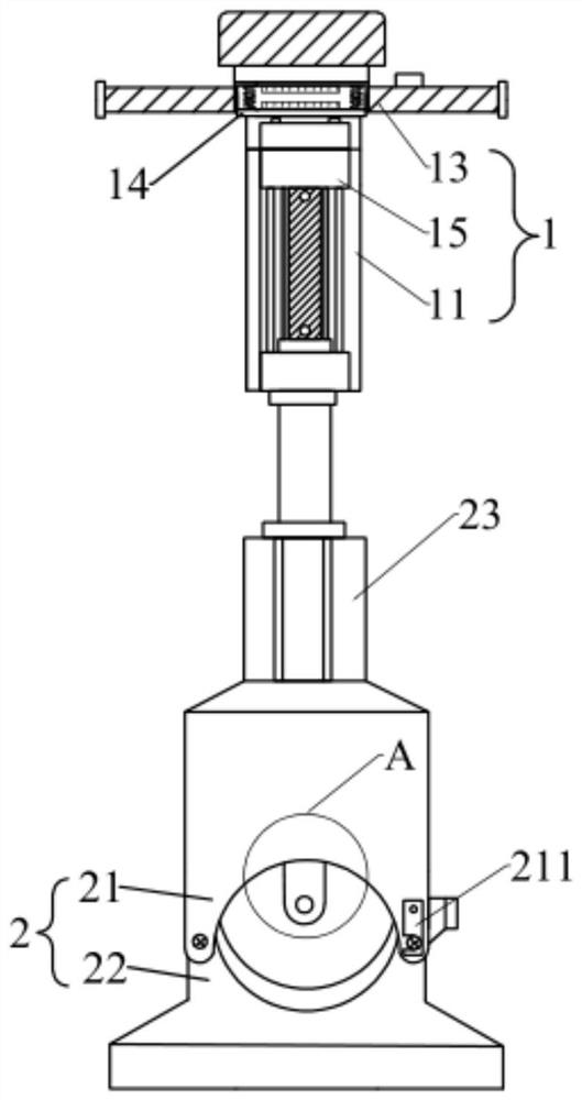
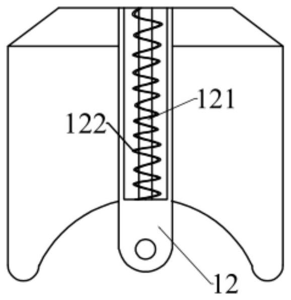
[0030] Such as Figure 1-Figure 2 As shown, the present invention provides a cable cutter, including a knife feeding mechanism 1 and a support 2, the knife feeding mechanism 1 includes a handle 13, a driving device 11 and a cutter 12, the handle 13 is installed on the driving device 11, and the driving Device 11 is provided with working end, and working end can move along vertical direction, and cutter 12 is installed on the working end; Driving device 11 is installed on the support 2, and support 2 comprises first support 21 and second support 22, and A support 21 is provided with a first installation groove, a second support 22 is provided with a second installation groove, one end of the first support 21 is rotationally connected with an end of the second support 22, and the other end of the first support 21 is provided with a lock Buckle 211, the lock buckle 211 can lock the other end of the first bracket 21 and the other end of the second bracket 22, so that the first ins...

Embodiment 2

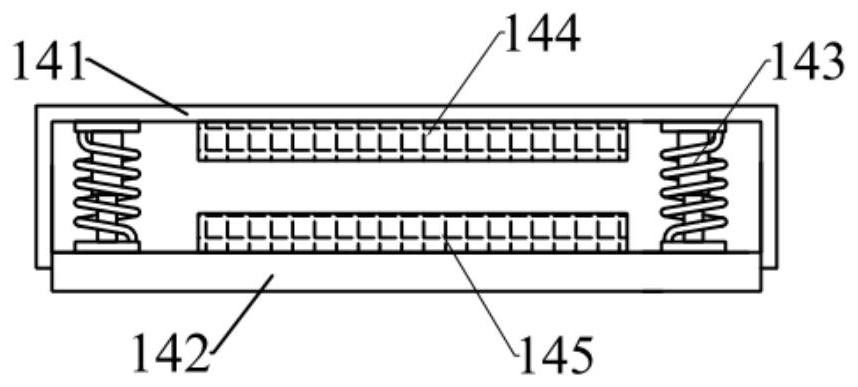
[0040] This embodiment provides a cable cutter, which is further improved on the basis of Embodiment 1. A shock absorbing device 14 is added to the knife feeding mechanism 1, which reduces the vibration and noise generated when the cable is cut, and reduces the noise. Shock device 14 such as image 3 shown.

[0041] Specifically, the knife feeding mechanism 1 also includes a shock absorber 14, and the shock absorber 14 includes a connecting block 141, a load bearing block 142 and a buffer portion 143, and the connecting block 141 is provided with a concave cavity with the opening facing downward, and the handle 13 is arranged on On both sides of the connection block 141, the load-bearing block 142 is fixedly installed on the driving device 11, the buffer portion 143 is located in the cavity, one end is connected to the connection block 141, and the other end is connected to the load-bearing block 142, and the load-bearing block 142 can be deformed in the concave cavity. Slidi...


PUM


Abstract

The invention belongs to the technical field of electric power engineering construction, and discloses a cable cutter. The cable cutter comprises a cutter feeding mechanism and a support, wherein thecutter feeding mechanism comprises a grip, a driving device and a cutter; the grip is mounted on the driving device; the driving device is provided with a working end; the working end can move in thevertical direction; the cutter is mounted at the working end; the driving device is mounted on the support; the support comprises a first support and a second support; a first mounting groove is formed in the first support; a second mounting groove is formed in the second support; one end of the first support is rotationally connected with one end of the second support, a lock catch is arranged atthe other end of the first support, the lock catch can lock the other end of the first support and the other end of the second support, a groove opening of the first mounting groove and a groove opening of the second mounting groove are opposite, a working cavity is formed, and the cutter can move up and down in the working cavity. The cable cutter is simple in overall structure, can effectivelyfix a cable, improves the cutting efficiency of the cable, avoids contact between a hand and the cutter, and is high in safety performance.

Description

technical field [0001] The invention relates to the technical field of electric power engineering construction, in particular to a cable cutter. Background technique [0002] The cable is twisted by several or several groups of mutually insulated conductors, often twisted around a center, covered with a highly insulating covering layer, and is often erected in the air or installed underground or underwater for telecommunications or power delivery. When installing the cable, the cable will be cut according to the needs of the construction site. The commonly used wire cutter needs to place the human hand on the handle of the wire cutter to cut the cable manually, which is time-consuming, laborious and insufficient in safety. The existing cable cutting device The structure is huge and the interior is intricate. When using it, it needs to be deployed in time on site. The conditions of use are limited. Contents of the invention [0003] The object of the present invention is ...

Claims


Application Information

Patent Timeline
IPC IPC(8): H02G1/00
CPCH02G1/005
Inventor 陈广华莫灿明王伟兴黄迪莎
Owner GUANGDONG POWER GRID CO LTD
Why Eureka
Try Eureka